NetSure
™
-48V DC Power System
User Instructions, UM582127000 (Issue AD, January 20, 2014)
Spec. No: 582127000 Code: UM582127000
Model No: 721NPBB Issue AD, January 20, 2014
Optional LVD Driver Circuit Card
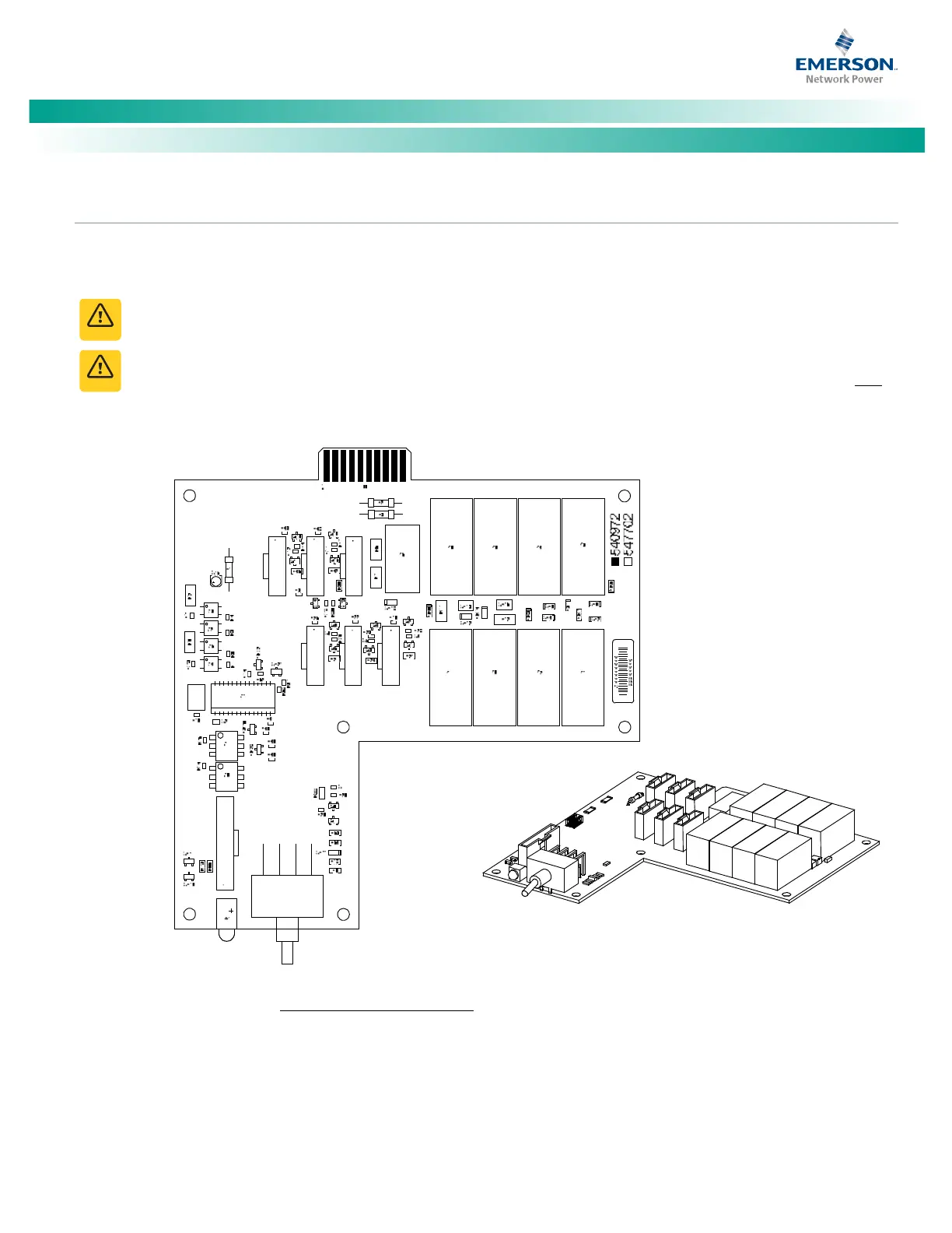
The optional LVD driver circuit card installed in the main bay contains an LVD inhibit switch and indicator. Refer to Figure 3. LVD driver
circuit cards are required for 2-, 3-, or 4-row distribution cabinets that contain three or more LVD contactors (LVBD and/or LVLD); or if the
distribution cabinet is equipped with an LVBD contactor rated 1200A or higher.
If the switch is returned to the ON (normal) position when low voltage disconnect alarms are active, a low voltage
disconnection will occur.
While the LVD inhibit switch is in the OFF (inhibit) position, a low voltage disconnection will not occur if battery or
load voltage decreases below the low voltage disconnect setpoint. For maximum battery protection, this switch should NOT
be left in the OFF (inhibit) position.
Figure 3. Optional LVD Driver Circuit Card
LVD Inhibit Sw
itch
Momentary
UP / Middle / Dow
n
Momentary
UP Position: Clos
es all LVD Contac
tors (i
nhibit mode).
Middle
Position: O
FF (ACU+ DOES NOT contr
ol LVD’s) (in
hibit mode).
DOWN
Position: ON (ACU+ con
trols LVD’s).
LVD Inhi
bit
Active Indicator
Illuminates
when th
e
low voltage dis
connec
t
circu
it has been disable
d
thr
ough the use of the
LVD Inhibit swi
tch.
J6 J5
J4
J3 J2 J1
J9
J
7
S
1
Note: T
he UP positio
n will no
t close the LVBD
contactor
if the bat
tery is manually
disconn
ected using the
Manual Batt
ery Disconnect S
witch.
Switch an
d indica
tor located
on circuit c
ard inst
alled in
Main Bay onl
y.

 Loading...