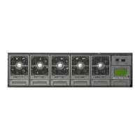
NetSure
™
-48V DC Power System
User Instructions, UM582127000 (Issue AD, January 20, 2014)
Spec. No: 582127000 Code: UM582127000
Model No: 721NPBB Issue AD, January 20, 2014
can change the identification number, see “Configuring the ACU+
Identification of Rectifiers” or “Configuring the ACU+ Identification
of Converters” in the separate Power System Installation Manual
(IM582127000).
Replacing a Rectifier or Converter Module (in a Spec. No.
588705300 Shelf)
Refer to the Rectifier User Instructions (UM1R482000E3) or
Converter User Instructions (UM1C48241500) for a rectifier and
converter module replacement procedure. Refer also to “System
Troubleshooting Information” on page 18.
The rectifier or converter module being replaced is assigned by the
ACU+ the lowest available identification number. If desired, you
can change the identification number, see “Configuring the ACU+
Identification of Rectifiers” or “Configuring the ACU+ Identification
of Converters” in the separate Power System Installation Manual
(IM582127000).
Replacing the ACU+ Controller
Refer to the ACU+ Instructions (UM1M820BNA or
UM1M820DNA400) for a controller replacement procedure.
Replacing a Distribution Device
General
Replace distribution devices with the same type and rating. Refer
to System Application Guide SAG582127000 for part numbers.
Distribution Fuse “Alarm Fuse” Replacement
If a distribution fuse opens, the associated alarm fuse opens.
Replace the distribution fuse before replacing the alarm fuse.
PROCEDURE
1. An alarm fuse is removed by pulling it straight out of the
fuseholder. If the alarm fuse is located in a modular fuse
carrier, hold the fuse carrier in place with your thumb
while pulling on the alarm fuse to prevent the entire
carrier from inadvertently being pulled out.
2. Safety fuse covers are provided for all Bussmann GMT
type fuses installed in the system. These covers snap
onto the fuses and provide protection from exposed
electrical terminations when a fuse opens. Insure that
the safety fuse cover is installed after replacing a fuse.
Refer to Figure 12for installation details.
Figure 12. Installation of Safety Fuse Covers
Replacing a TPS/TLS Fuse
PROCEDURE
Refer to Figure 13 as this procedure is performed.
1. Open the distribution cabinet’s front door by turning the
latch in the counterclockwise position.
2. Remove the fuse carrier from the mounted fuseholder
body by pulling it straight out.
3. Remove the open fuse from the fuse carrier and replace it
with the same type and rating.
4. Replace the alarm fuse located in the front of the fuse
carrier with the same type and rating. Ensure that a
plastic safety cover is installed on the alarm fuse.
5. Push the fuse carrier securely back into the mounted
fuseholder body. Note that a polarizing key on the
bottom of the carrier prevents the carrier from being
inserted upside down.
6. Verify no Fuse Alarms are active.
7. Close the distribution cabinet’s front door. Turn the latch
clockwise to secure the door.
Replacing a Bullet Nose Fuseholder
PROCEDURE
Refer to Figure 13 as this procedure is performed.
1. Open the distribution cabinet’s front door by turning the
latch in the counterclockwise position.
Safety Cover
P/N 248898700
(GMT-X)
Safety Cover
P/N 102774
(GMT-Y)
 Loading...


