4. While pulling up on the hanger ball, securely
tighten the two setscrews in the motor coupling (Figure 1).
NOTE: The setscrew must be properly installed as
described above, or fan wobble could result.
5. The fan comes with blue, black and white leads that
are 42-inches long. Before installing the fan, measure
up approximately 6 to 9-inches above top of hanger
ball/downrod assembly. Cut off excess leads and
strip back insulation 1/2-inch from end of leads.
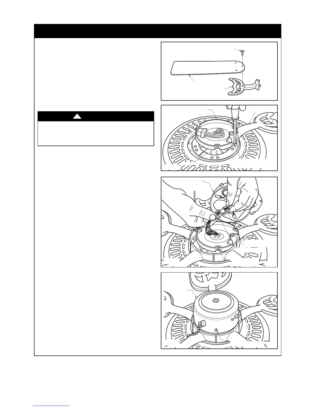
6. Mount the blade flanges to fan blades using three
M5 x 6 washer head blade screws per blade
(Figure 2).
Figure 5
NOTE: Take care not to scratch fan housing when
installing blades.
NOTE: Remove and discard the four shipping spacers
and screws from the motor hub.
7. Turn the fan assembly upside down in preparation for
mounting the fan blade assemblies.
8. Rotate the motor hub until the flange screw hole is next
to the cutout in the switch housing plate. Attach the
blade assembly to the motor hub using the two M6 x 14
flange screws preassembled in flange (Figure 3). Make
sure all screws are tightened. Repeat this procedure for
the other four blade assemblies.
9. The blade flanges have an interlocking feature that
must be fully engaged before tightening the screws.
Make sure all the flanges are properly engaged and
then tighten the flange screws. If one of the flanges
does not seat properly on the motor hub, loosen the
adjacent flange screws, re-engage and reseat the
flanges, then tighten the screws again.
10. Engage the connector of the switch housing assembly
with the motor connector (Figure 4). The two
connectors are keyed and color-coded and must be
mated correctly (color-to-color) before they can be
engaged. Make sure the connector latch closes
properly.
11. Remove the three switch housing mounting screws
(Figure 4) from the switch housing plate. Position the
switch housing assembly on the switch housing plate
and align the holes in the switch housing assembly
with the holes in the plate. Secure the switch housing
assembly by installing the three mounting screws
(Figure 5).
NOTE: Do not pinch wires between the switch
housing assembly and the switch housing plate.
12. You have now completed the assembly of your new
ceiling fan. You can now proceed with hanging and
wiring your fan.
5
emersonfans.com
Please contact 1-800-654-3545 for further assistance
U.L. Model No.: 52-ANT
3. Ceiling Fan Assembly (continued)
To reduce the risk of personal injury, do not bend the
blade flange when installing the blade flanges,
balancing the blades or cleaning the fan. Do not insert
foreign objects in between rotating fan blades.
WARNING
!
 Loading...