9. Install supplied O-ring in the O-ring groove of the new control.
Remove "knockout plugs" from the junction box or electrical
enclosure of the new control.
Onscrollcompressors,installinjectiontubeperdiagram–notethatit
installs at a slight angle (Figure 2). Thread tube in handtight and tighten
½ turn with a wrench or pliers.
10. With the solenoid off, mount and level the new control to existing
adapter using 1/4 - 20 UNC-2A x 3/4" long bolts:
A.IfreplacinganOMBoranOMC,turntheringedadapterange
approximately 1/4 turn counterclockwise to provide the correct three
(3) hole alignment since the holes are not equidistant.
(Important: If the current adapter has an O-ring groove, replace with
the correct adapter for the application - see catalog.)
B. If replacing an OMC CO
2
,allve(5)holesbetweentheadapterand
control should be alligned correctly.
Be sure that the O-ring has not fallen out of the groove and tighten
bolts evenly to 40 in.-lbs.
11. Reconnect the oil inlet line.
12. With pressure valved off, remove gauge manifold, cap ports, open
service valves and check for leaks.
13. If reconnecting an OMB refer to step A, if connecting an OMC refer to
step B
A. (OMB) Reconnect electrical power following color code and install
solenoid coil and power plugs. Note: Do not energize solenoid coil
before replacing on enclosing tube.
B. (OMC) Remove cover and refer to wiring schematic below to
reconnect power following color codes. Replace cover and assemble
screws to hand tight using #1 Phillips screwdriver. Note: Do not use
electronic screwdriver.
14. Check that the green LED is on. Yellow LED should come on after
about 10 seconds.
15.Checkthatthesolenoidisenergizedandthatthecontrolislling.
(Note:Ifcrankcasedoesnotllin2minutes,theredLEDshouldcome
on.)(Solenoidremainsontocontinuelling.)Ifthealarmtripsbefore
thecrankcaseislledto½sightglass,removepowertooilcontrolfor
several seconds and reinstall to reset alarm. If OMB, disconnect power
by removing power plug. If OMC, refer to wiring schematic below.
Compressorshouldthenllto1/2sightglassandyellow"ll"LED
should go out.
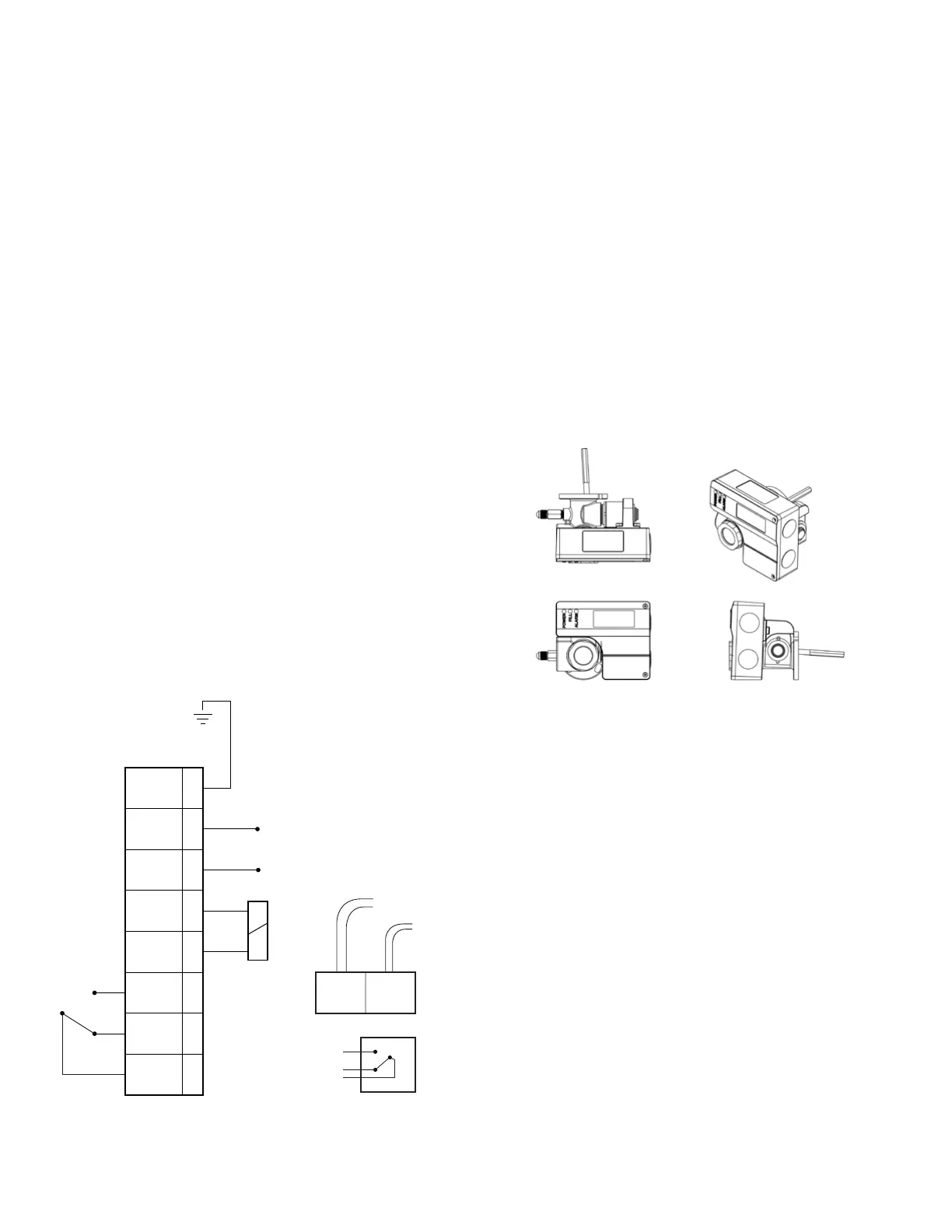
OMC
FIGURE 2
Note: Use of crimp type wiring connectors is highly recommended. If
wire nuts must be used, taping joint after assembly with electrical tape is
required.
Technical Support: 1 888 725 9797
PA-00388 (4/18) Emerson is a trademark of Emerson Electric Co. ©2018 All rights reserved. Emerson.com/White-Rodgers
16. Restart the compressor using the reverse procedure to shutting
it down.
17. Recheck for leaks and repair if necessary.
Important: Injection tube is not used on reciprocating compressors
where the control is mounted directly to the crankcase.
LED Codes When Lit:
Green –PowerissuppliedtoOMB/C.
Yellow –Floatsensordeterminedthattheoillevelhasbeenbelow
½ sight glass for over 10 seconds. Fill solenoid has been activated.
Red (continually lit)–Oillevelhasremainedbelow½sightglassfor
overtwominutesafterllsolenoidhasbeenactivated.Alarmhasbeen
activated and compressor is prevented from operating until oil level
reaches ½ sight glass when alarm automatically resets.
Red (ashing)–Therehavebeenveautoresetalarmsregisteredwithin
a 30 minute period. Alarm circuit is now locked on and compressor locked
off. Fill solenoid is de-energized. Alarm remains locked in until power lead
is manually unplugged and again plugged back into device.
Note: OMB/C units used on scroll compressors require the use of an
injection tube this tube is shipped wired to the unit but not installed.
It is to be screwed into the rear of the unit, and tightened hand tight
plus one half turn. When properly installed, the tube will be at a slight
angle relative to the OMB/C . See gure 2 below.
OMBOMC
FIGURE 1
Electrical Wiring Diagram
8
7
6
5
4
3
2
1
Relay
Common
Closed in Alarm
Open in Alarm
Factory
Wired
Norm
Closed
Norm
Open
PE
GND
Solenoid
Solenoid
L2 L2
L1 L1
Supply
Voltage
Solenoid
Alarm Contacts
Factory Wired
to Coil
To Transformer
24 VAC
Orange - Common
Brown - Open in Alarm
Red - Closed in Alarm

 Loading...


