ROC364 Instruction Manual
3-18 Input and Output Modules Rev Jun/05
NOTE: The RTD module input can be calibrated before installing it in the field when short wire
runs will be used, but if the RTD module is used as a temperature input to a flow calculation,
then the RTD should be calibrated at the same time as the pressure inputs.
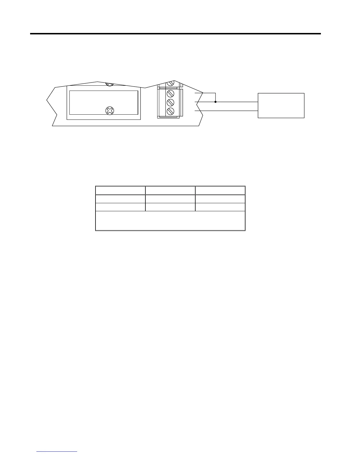
A4464821
1
ABC
DECADE BOX
RTD
WHTC
WHT
RED
B
A
Figure 3-21. Calibration Setup
Table 3-1. Calibration Resistance Values
ALPHA –50ºC (58ºF) 100ºC (212ºF)
0.00385 80.31 Ohms 138.50 Ohms
0.00392 79.96 Ohms 139.16 Ohms
NOTE: Resistance values for RTD probes with other alpha
values can be found in the temperature-to-resistance
conversion table for that probe.
1. Connect the decade box as shown in Figure 3-21.
2. Set the decade box to the –50°C (–58°F) resistance value corresponding to the RTD alpha value
in Table 3-1.
3. Enter the value displayed for “Raw A/D Input” as the value for “Adjusted A/D 0%” using the
Analog Inputs configuration screen for the RTD input. Refer to ROCLINK > Configure > I/O >
AI Points Advanced tab.
4. Set the decade box to the 100°C (212°F) resistance value given in Table 3-1.
5. Enter the value displayed for “Raw A/D Input” as the value for “Adjusted A/D 100%” using the
Analog Inputs Advanced configuration screen for the RTD input.
6. Enter –50°C (–58°F) for “Low Reading EU” using the Analog Inputs configuration screen. Refer
to ROCLINK > Configure > I/O > AI Points General tab.
7. Enter 100°C (212°F) for the “High Reading EU” using the Analog Inputs configuration screen.
8. Click Apply to save the changes.
 Loading...