February 2019
14
Quick Start Guide
Figure 8. Load Limitation
Maximum loop resistance = 43.5 x (Power supply voltage – 10)
HART communication requires a minimum loop resistance of 250 ohm.
4.4 Wiring diagrams
Figure 9. Point-to-Point
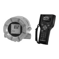
A. Field Communicator or PC with HART modem
B. Rosemount 520
Table 5. Load Resistance and Voltage Supply Limits
Parameter Limit
R
1
() 250
R
2
( ) 1130
V
min
(V) 10
V
1
(V) 15.75
V
2
(V) 36
~
A
B
00825-0100-4520_RevAC.fm Page 14 Thursday, February 7, 2019 10:16 AM






 To Next Page
