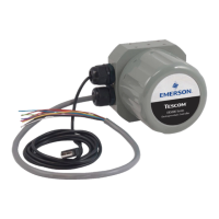
ER5000 —
33
How It Works
• The second driver notices that there is a full cup of hot coffee
in the cup holder. This driver will take the curve as widely
and as slowly, as possible, because this driver’s primary goal
is to make sure the hot liquid does not spill. This controller
has lowered the Proportional and Integral and increased the
Derivative, to make the response as stable as possible, at the
expense of some speed and precision.
• The third driver is participating in a road race. This driver will
take the curve as tight and fast as possible, pushing the limits
right up to the point of spinning the car out of control. This
controller has maxed out the Proportional and Integral to get
the fastest response possible, then set Derivative just enough
to reestablish control at the end.
Three controllers, three different goals, three different responses
to the same change. By raising and lowering the relative amounts
of Proportional, Integral and Derivative (a process called Tuning
the controller) you can set up your ER5000 to meet the specic
response characteristics and work within the specic limitations,
of any system.
A Typical PID Control System
Figure 2 shows a simplied diagram of a typical PID
control system.
In this drawing, the dashed line represents the controller. The
setpoint (r) is sent from the internal board or an external source.
The feedback (y) is sent from internal or external sensors that
monitor the current state of the system. The controller reads
both values and subtracts the feedback signal from the setpoint.
+-
Setpoint = r
Controller
Error = e
Output
Feedback = y
System
Under
Control
Figure 2: Simplified PID Control System

 Loading...


