ER5000 —
78
Installation Variations
ER5000 Installation Variations — Wiring Diagrams
The ER5000 has a wide range of wiring options, allowing it to be congured for virtually any application requirement. If your application calls for a variation on the
standard installation, use the diagrams on the following pages to build a complete conguration. Note that in your actual application, multiple wires may terminate
at the same connection: for example, the violet wire (Pin 7), which is the (+) connection to the power source, may also connect directly to the transducer or other
external devices.
If your application requires a Hazardous Location model (ER5050), read Installing a Hazardous Location
Model (ER5050) on page 110 before following the steps listed below.
Step 1: Connect the ER5000 to a
24V DC Power Supply
All wiring congurations begin by
connecting the ER5000 to a 24V DC
power supply. The external power
supply is necessary for the controller to
operate and is part of all applications.
Power Supply page82
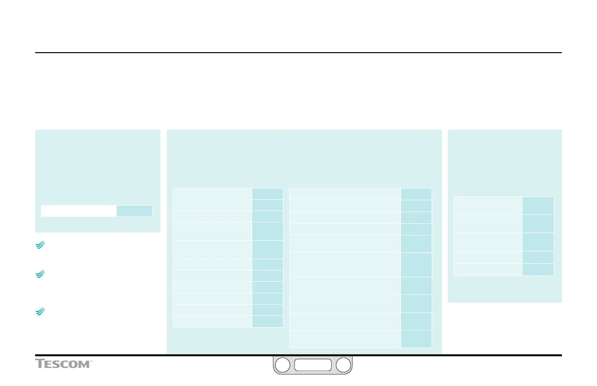
Step 2: Connect the Setpoint and Feedback Source
Setpoint and feedback sources vary with application. Use the links below to match the setpoint and
feedback sources for your application to specic wiring diagrams and descriptions in this section.
Click a page number to go to that diagram; click the BACK button to return to this page.
Setpoint Source
Prole None
Analog (Potentiometer) page83
Analog (Current/Voltage) page84
Analog
(Passive PC or PLC D/A Card)
page85
Analog
(Active PC or PLC D/A Card)
page86
Prole with External Control page87
Digital
(RS232 to RS485 Converter)
page89
Digital
(USB to RS485 Converter)
page90
Digital
(RS232 to RS485 Network)
page91
Digital
(USB to RS485 Network)
page93
Digital (USB) USB cable
Feedback Source
Internal None
Two Wire Transducer page95
Three Wire Transducer page96
Four Wire Transducer page97
4–20 mA External Feedback, Floating Input,
Feedback Signal Monitored by PC or PLC A/D Card
page98
4–20 mA External Feedback, Ground
Referenced Input, Feedback Signal Monitored
by PC or PLC A/D Card
page99
Two Wire Transducer, PC/PLC Used to Monitor
Voltage Through ER5000 Internal Resistor
page100
Three Wire Transducer, PC/PLC Used to Monitor
Voltage Through ER5000 Internal Resistor
page101
Four Wire Transducer, PC/PLC Used to Monitor
Voltage Through ER5000 Internal Resistor
page102
Switch Feedback Control to a Second Feedback
Source
page103
Step 3: If Applicable, Connect
Wiring for Additional Functions
Some applications call for
monitoring and control connections
in addition to the standard trio of
power, setpoint and feedback.
Monitoring Additional
Analog Inputs
page104
Monitoring the Internal
Sensor, 4–20 mA Wiring
page105
Monitoring the Internal
Sensor, 0–10V Wiring
page106
Digital Outputs page107
Suspend Mode page109
NOTENOTE
CAUTIONCAUTION
WARNINGWARNING
This section shows variations to the
typical ER5000 conguration described in the
Getting Started section.
NOTENOTE
CAUTIONCAUTION
WARNINGWARNING
The (+) and the (-) in the tables and
gures of this section refer to the differential
inputs. Both must be connected for the system
to work properly.
NOTENOTE
CAUTIONCAUTION
WARNINGWARNING
Setpoint is set digitally by writing to
variable #37 (ID_SETPOINT), using the ERTune
™
program or your own coding. Refer to the Internal
Variables and the ER5000 Software Development
Support sections for more information.

 Loading...

