10 Unidrive M400 Quick Start Guide
Issue Number: 5
Table 3-1 Tools required
Table 3-2 Recommended torque settings
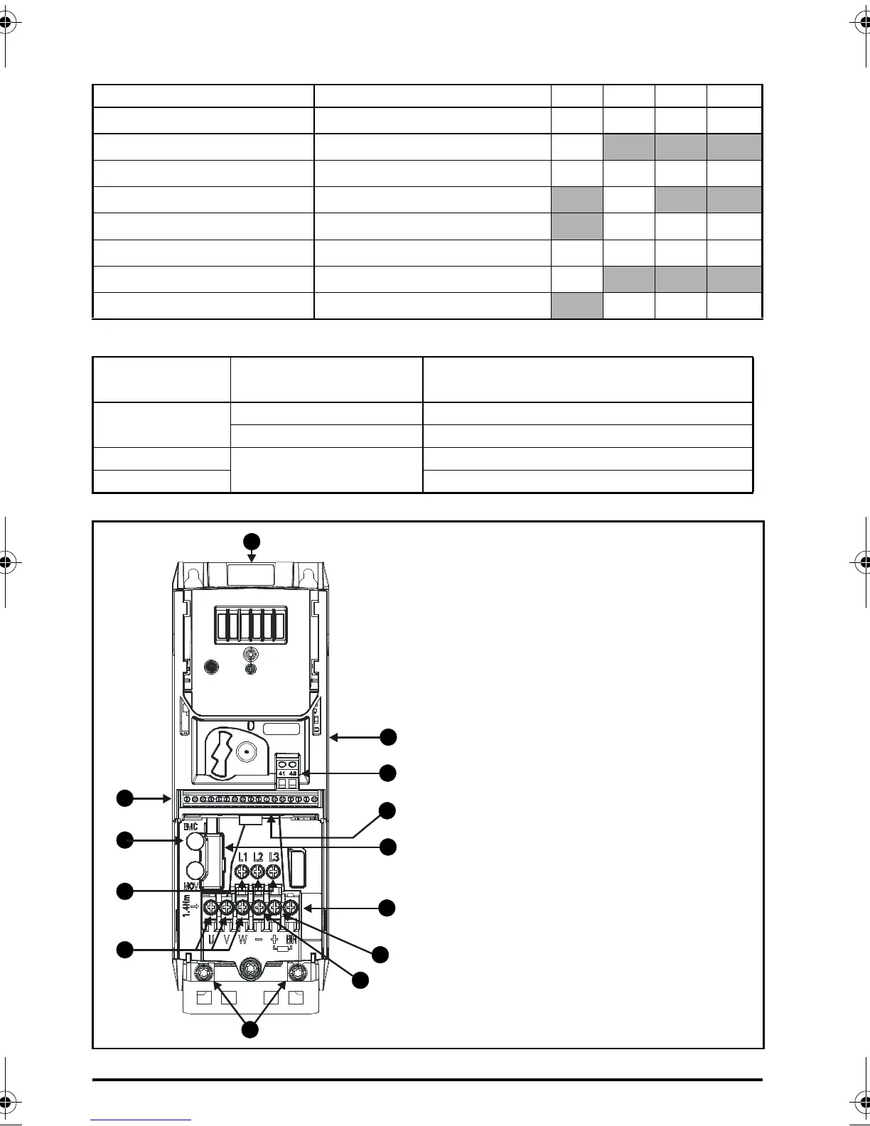
Figure 3-1 Feature diagram (size 2 shown)
Tool Location Size 1 Size 2 Size 3 Size 4
Small terminal screwdriver Control, relay and STO terminals
9999
3mm Flat-bladed screwdriver Power terminals
9
5mm Flat-bladed screwdriver Terminal cover
9999
Pozidrive 1 screwdriver AC power terminals
9
Pozidrive 2 screwdriver Power terminals
999
Torx 10 driver EMC & MOV screws
9999
Torx 15 driver Fan screw
9
Torx 20 driver Fan screw
999
Model size
Terminal block
description
Torque settings
All
Control terminals 0.2 N m (0.15 Ib ft)
Relay terminals 0.5 N m (0.37 Ib ft)
1
Power terminals
0.5 N m (0.37 Ib ft)
2, 3, 4 1.4 N m (1.03 Ib ft)
Key
1. Rating label (On side of drive)
2. Identification label
3. Option module connection
4. Relay connections
5. Control connections
6. Braking terminal
7. Internal EMC filter screw
8. DC bus +
9. DC bus -
10. Motor connections
11. AC supply connections
12. Ground connections
13. SAFE TORQUE OFF
connections
Unidrive M400 Quick Start Guide English Iss3.book Page 10 Wednesday, July 16, 2014 8:12 AM

 Loading...


