Unidrive M700/M701 / Unidrive HS70/HS71 Control Getting Started Guide 9
Issue Number: 2
Control connections Introduction
Control connections
Getting started
Basic parameters
(Menu 0)
Running the motor Further information
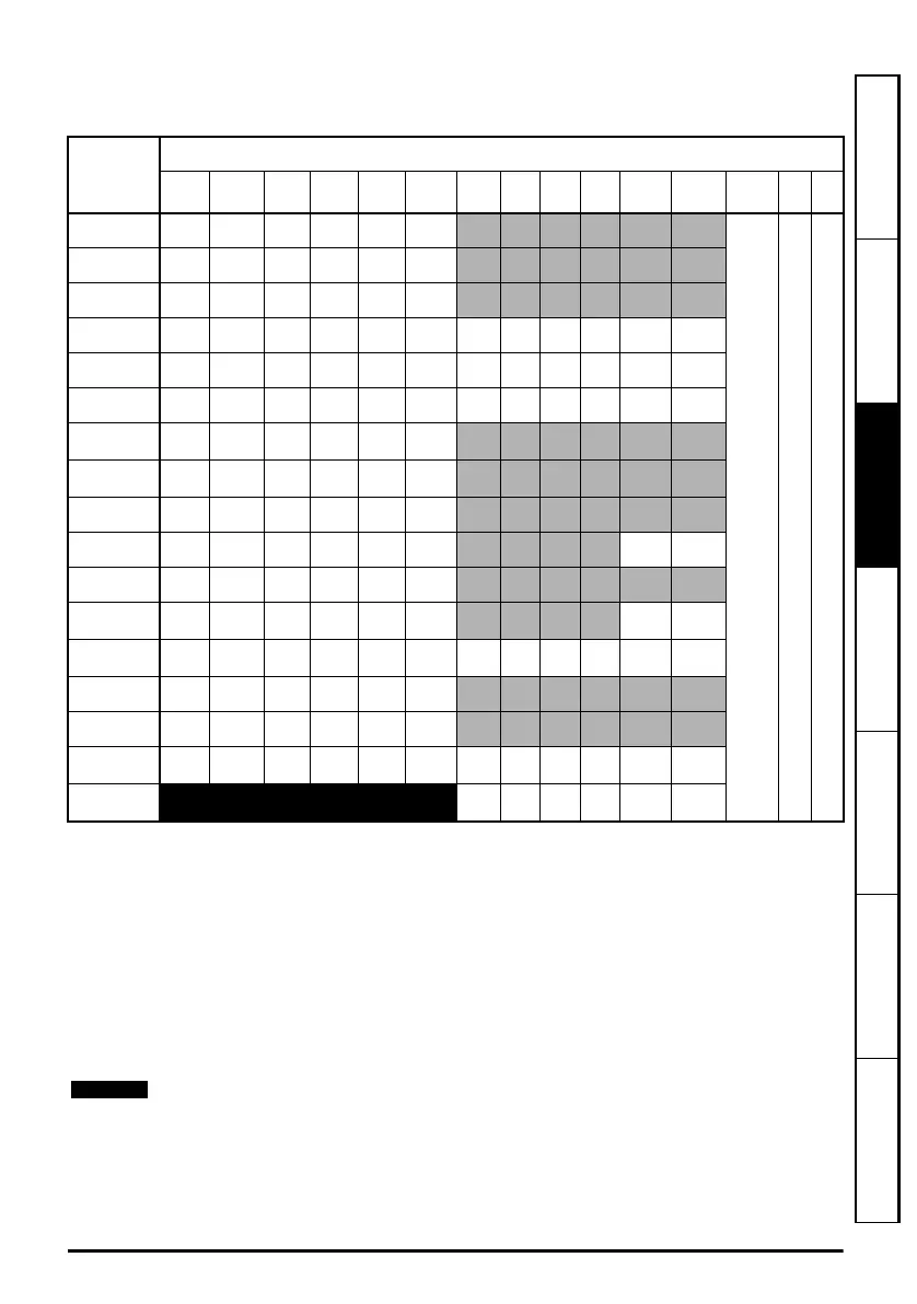
3.1.1 Position feedback connection details
Table 3-1 P1 position feedback connection details
*
1
- One sine wave per revolution
*
2
- One cosine wave per revolution
*
3
- Freeze inputs are shown in the table above as ‘Frz’.
*
4
- The encoder power supply is selectable through parameter configuration to 5 Vdc, 8 Vdc and
15 Vdc.
Th - Thermistor input.
Greyed cells are for P2 position feedback connections or simulated encoder outputs. Refer to the
Drive User Guide for further information.
P1 Position
feedback
interface
Pr 03.038
Connections
123456789101112131415
AB (0) A A\ B B\ Z Z\
+V
*4
0 V Th
FD (1) F F\ D D\ Z Z\
FR (2) F F\ R R\ Z Z\
AB Servo (3) A A\ B B\ Z Z\ U U\ V V\ W W\
FD Servo (4) F F\ D D\ Z Z\ U U\ V V\ W W\
FR Servo (5) F F\ R R\ Z Z\ U U\ V V\ W W\
SC (6)
A
(Cos)
A\
(Cos\)
B
(Sin)
B\
(Sin\)
ZZ\
SC
Hiperface (7)
Cos Cosref Sin Sinref DATA DATA\
EnDat (8) DATA DATA\ CLK CLK\
Frz*
3
Frz\*
3
SC EnDat (9) A A\ B B\ DATA DATA\ CLK CLK\
SSI (10) DATA DATA\ CLK CLK\
Frz*
3
Frz\*
3
SC SSI (11)
A
(Cos)
A\
(Cos\)
B
(Sin)
B\
(Sin\)
DATA DATA\ CLK CLK\
SC Servo
(12)
A
(Cos)
A\
(Cos\)
B
(Sin)
B\
(Sin\)
ZZ\UU\VV\WW\
BiSS (13) DATA DATA\ CLK CLK\
Frz*
3
Frz\*
3
Resolver (14) Cos H Cos L Sin H Sin L Ref H Ref L
SC SC (15)
A
(Cos)
A\
(Cos\)
B
(Sin)
B\
(Sin\)
ZZ\
C*
1
C\*
1
D*
2
D\*
2
Frz2*
3
Frz2\*
3
Commutation
Only (16)
UU\VV\ W W\
Frz and Frz\ on terminals 5 and 6 are for Freeze input 1. Frz2 and Frz2\ on terminals 11
and 12 are for Freeze input 2.
Unidrive M700_M701 Getting Started Guide English iss7.book Page 9 Friday, December 12, 2014 1:14 PM
 Loading...


