16
b) Meter for direct connection up to 60 A
DANGER!
Inproper installation endangers life and health and carries the
risk of malfunction and property damages!
y Use a selective overcurrent protection for 63 A according to the
applicable TAB (e.g. a main circuit breaker) before the meter.
y Secure the connecting paths in accordance with the applicable
technical regulations and in accordance with the power specication
on the name plate of the meter.
y The installer bears responsibility for coordinating the rated values
and parameters of the supply-side overcurrent protection devices
with the maximum rated currents as well as the rated consumption
category of the meter system for directly connected meters.
y The connection cables used to connect a meter must be selected to
match the maximum load of the meter and the installation environ-
ment in terms of type, cross-section, voltage and temperature.
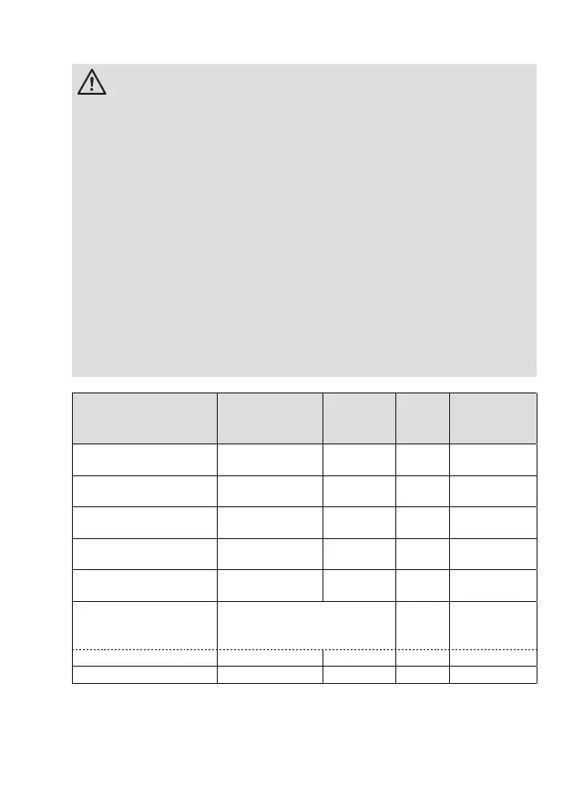
Meter up to 60 A
Current
terminals
1, 3, 4, 6, 7, 9
N-
terminal
10, 12
N-tap
11
Additional
terminals
Terminal dimension
W x H or d (mm)
7,5 x 9,5 7,2 3,2 2,6 x 2,2
Minimum connection
cross section (mm²)
10,0 10,0 1,0 1,0
Maximum connection
cross section (mm²)*
25,0 25,0 2,5 2,5
Minimum torques for
terminals (Nm)
4,0 4,0 — —
Maximum torques for
terminals (Nm)
5,0 5,0 0,5 —
Screw type
Screw and washer assembly
with cross recess, Type PZ2
(acc. to ISO 4757)
Slotted
screw
Spring load-
ed terminal
Thread size
M8 M6 M3 —
Stripping length (mm)
14,0 14,0 6,0 5,0
* Rated connection capacity acc. to EN 60999-1
 Loading...