Do you have a question about the EMKO ESM-3700 and is the answer not in the manual?
Overview of the installation process, including physical and electrical aspects.
Details user interface, parameter access, and descriptions for device operation.
Explains symbols used for safety warnings, dangerous situations, and important notes.
Lists standard and optional power supply, process input types, and alarm outputs.
Provides codes and options for configuring and ordering the ESM-3700 unit.
Outlines warranty period, conditions, and maintenance guidelines for the device.
General safety precautions and preliminary steps before installation.
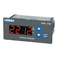
Describes the ESM-3700 device, its front panel, dimensions, and mounting clamp for models with alarm.
Displays front panel view, dimensions, and panel cut-out dimensions for models without alarm output.
Details operating conditions, temperature, humidity, altitude, and panel mounting procedures.
Explains how to use fixing clamps and procedures for removing the device from the panel.
Illustrates the terminal layout and provides instructions for electrical connections.
Provides a detailed wiring diagram for power supply, process input, and alarm outputs.
Shows device labels for models with and without alarm output, detailing connections.
Explains how to connect the device to the power supply, including fuse and switch recommendations.
Details connections for serial and 3-wire transmitters with current output.
Describes connecting voltage output transmitters and galvanic isolation test values.
Illustrates connections for Relay Output and SSR Driver Output.
Identifies controls and indicators on the front panel for devices with alarm output.
Identifies controls and indicators on the front panel for devices without alarm output.
Explains software revision display and the procedure for changing alarm set values.
Lists parameters for process input type, filter, display function, and decimal point.
Illustrates operation graphics for alarm output and alarm types (High/Low).
Provides a flowchart for accessing programming mode parameters on devices with alarm output.
Provides a flowchart for accessing programming mode parameters on devices without alarm output.
Step-by-step guide on entering programming mode, changing, and saving parameters.
| Brand | EMKO |
|---|---|
| Model | ESM-3700 |
| Category | Touch Panel |
| Language | English |