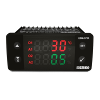
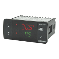
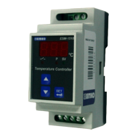
3.1 Terminal Layout and Connection Instructions
You must ensure that the device is correctly configured for your application.
Incorrect configuration could result in damage to the temperature being
controlled, and/or personal injury. It is your responsibility, as the installer, to
ensure that the configuration is correct.
Device parameters has factory default values. These parameters must be set
according to the system’s needs.
Only qualified personnel and technicians should work on this equipment. This
equipment contains internal circuits with voltage dangerous to human life.
There is severe danger for human life in the case of unauthorized intervention.
Be sure to use the rated power supply voltage to protect the unit against
damage and to prevent failure.
Keep the power off until all of the wiring is completed so that electric shock and
trouble with the unit can be prevented.
3.Electrical Wirings
c
c
c
c
a
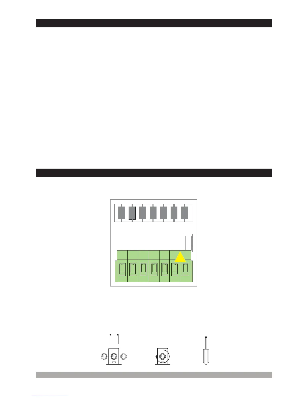
Torque
0.5 Nm
Max. 2.5 mm / 0.098 inch
Wire Size:
14AWG/1 mm²
Solid /Stranded
Screw driver
0.8x3mm
12
 Loading...