
D
Douglas BurnsSep 13, 2025
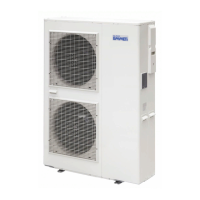
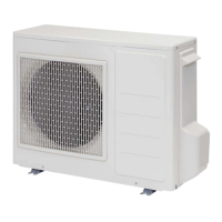
How to fix emmeti MIRAI SMI 4.0 Heat Pump that does not start re-operation immediately?
- JJames Ross MDSep 13, 2025
After stopping, the emmeti Heat Pump will not restart immediately for approximately 3 minutes. This is to protect the system.