4
Icon Description Meaning LED colour
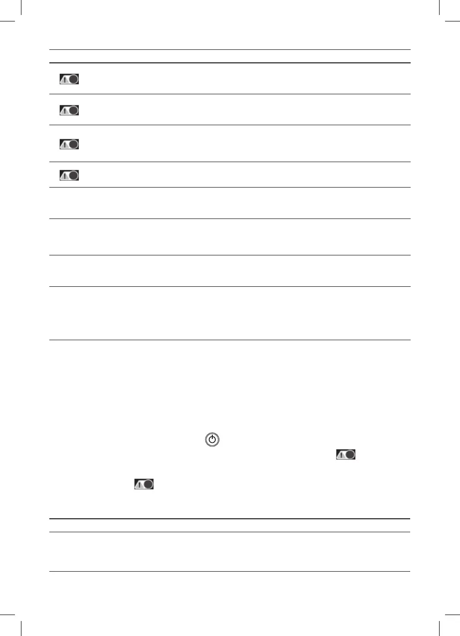
Error diagnostic indicator
Faulty or incorrect accumulator for charging.
This accumulator cannot be charged.
LED glows red
Error diagnostic indicator
The capacity of the battery may be too high for
the selected mode. Check the capacity of the
battery and the charging mode.
LED ashes yellow
Error diagnostic indicator
The voltage of the accumulator is too high or
low for the selected charging mode. Check
the voltage of the accumulator and the
charging mode.
LED glows yellow
Error diagnostic indicator
Reversed polarity. The connectors must be
connected to the correct polarity.
LED ashes red
25 % Accumulator charge level
LED will be ashing if the battery is charged
less than 25 %. If the battery is charged to
25 %, the LED will glow red.
Red LED
50 % Accumulator charge level
LED will be ashing if the battery is charged
less than 50 %. If the battery is charged to
50 %, the LED will glow orange.
Orange LED
75 % Accumulator charge level
LED will be ashing if the battery is charged
less than 75 %. If the battery is charged to
75 %, the LED will glow yellow.
Yellow LED
100 % Accumulator charge level
LED will be ashing if the battery is charged
less than 100 %. If the battery is charged to
100 %, the LED will glow green. The charger
will switch to STAGE 7 maintenance mode.
Other LEDs 25 %, 50 % and 75 % will stop
glowing.
Green LED
Charging Accumulator
1. Make sure the accumulator you are about to charge is a 6 V/12 V lead-acid accumulator or 4-cell LiFePO₄ 12.8 V accu-
mulator. Do not charge batteries with nominal voltage other than 6 V/12 V or 12.8 V.
2. Disconnect all appliances from the accumulator. If the accumulator is in a vehicle, turn o the ignition and all appliances.
Then disconnect cables, rst the negative terminal (-) black cable then the positive terminal (+) red cable.
3. Clean the terminals on the accumulator you are about to charge.
4. Connect the charger to the accumulator. Make sure to observe the correct polarity (+ pole is indicated in red, – pole in
black). First connect the red terminal (+) to the positive pole of the accumulator (+). Then connect the black terminal (-)
to the negative pole of the accumulator (-).
5. Plug the charger into a socket (220–240 V AC 50 Hz). There will be a short delay (1 to 3 s) after connecting the charger to
power before all LEDs light up. The LEDs lighting up for ca 0.5 s conrms they are working. After the check, the charger
starts in STANDBY mode, indicated by green LED
. In this mode, the charger does not generate any output current.
If the polarity of the cables leading to the accumulator is switched, a red LED error indicator
will be ashing. If
that is the case, connect the red terminal to the + pole and black terminal to the – pole of the accumulator. Protection
against reversed polarity protects both the accumulator and the charger against damage. If the accumulator is faulty
the error diagnostic LED
will be glowing. In that case, the accumulator cannot be recharged.
6. Before charging, you must select the correct charging mode for the accumulator. The charger has 3 charging modes.
Charging mode for LiFePO₄ 12.8 Vaccumulators, and 6 Vand 12 Vcharging mode for lead-acid accumulators. Follow
the table below to choose the correct charging mode:
Charging mode Accumulator capacity (Ah) Explanation
6 V 1,2–30 Ah
Charging 6 V lead-acid accumulators with liquid electrolyte –
WET, maintenance-free (MF), Ca/Ca, AGM and GEL.
Charging voltage 7.3 V
Charging current 0.8 A