Do you have a question about the EMPHASER EA4100-500 and is the answer not in the manual?
Covers 6-channel operation, independent filtering, and 1 ohm stability for versatile audio setups.
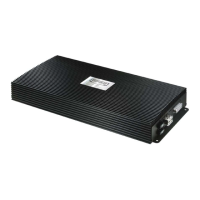
Features dash-mount remote, adjustable input sensitivity, external fuses, and status LEDs.
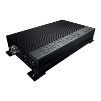
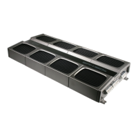
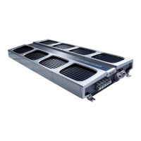
Highlights robust construction, advanced protection circuitry, and internal cooling fan.
Details RCA inputs, gain, and frequency controls for channels 1/2-CH, 3/4-CH, and 5/6-CH.
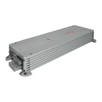
Covers power input terminals, remote input, speaker outputs, fuses, power LED, and protection LED.
Map out the complete audio system and wiring required for installation.
Select a secure mounting location with sufficient cooling and clearance.
Details on power, RCA, speaker cables and minimum impedance requirements.
Outlines safe mounting practices and the step-by-step procedure for installing the amplifier.
Run audio signal cables separately from power; connect remote lead and RCA interconnects.
Connect speaker cables to terminals, ensuring correct polarity and secure tightening.
Route positive power cable with fuse and attach ground cable securely to chassis.
Set operation modes for 1/2-CH and 3/4-CH channels based on connected speaker types.
Adjust the high-pass crossover frequency for satellite speakers, typically 50-150Hz.
Set crossover frequencies for kickbass speakers in 3/4-CH channels based on unit count.
Adjust the low-pass crossover frequency for the subwoofer, typically 60-90Hz for best results.
Set the subsonic high-pass frequency for the subwoofer system to match its size and function.
Set input gain controls for optimal dynamic response and fine-tune crossovers for tonal balance.
Use the phase shift control to match satellite and subwoofer sound phase for improved audio.
Detailed RMS power output at various impedance loads (4 Ohm, 2 Ohm, bridged) and channels.
Includes damping factor, signal-to-noise ratio, frequency response, and channel separation.
Covers active filtering specs, fuse rating, and physical dimensions (W x H x D).
Details exclusions like unauthorized installation or abuse and conditions for warranty claims.
Fields for amplifier model, serial number, and owner's contact details for warranty registration.
Sections for authorized dealer or self-installation approval and dealer stamp.
| Channels | 4 |
|---|---|
| THD @ 4 Ohms | <0.05% |
| Signal to Noise Ratio | >95dB |
| Input Sensitivity | 200mV - 6V |
| Frequency Response | 10Hz - 30kHz |