31449-4-1113 Page 73
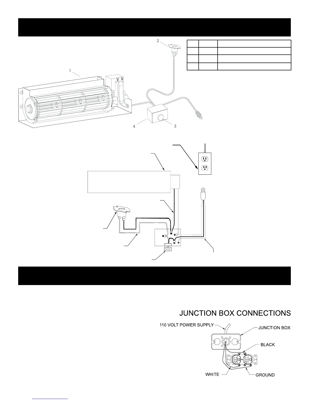
110 VOLT AC
JUNCTION BOX
WHITE
SPEED
CONTROL
FAN
SWITCH
GROUND
BLACK
FAN
1 R7731 BLOWER MOTOR
2 31920 SWITCH ASSEMBLY
3 R4192 SPEED CONTROL KNOB
4 R4186 SPEED CONTROL
FBB4 OPTIONAL VARIABLE SPEED BLOWER INSTALLATION
CAUTION: ALL WIRING SHOULD BE DONE BY A QUALIFIED ELECTRICIAN AND SHALL BE IN COMPLIANCE WITH ALL LOCAL,
CITY AND STATE BUILDING CODES. BEFORE MAKING THE ELECTRICAL CONNECTION, MAKE SURE THAT MAIN POWER SUP-
PLY IS DISCONNECTED. THE APPLIANCE, WHEN INSTALLED, MUST BE ELECTRICALLY GROUNDED IN ACCORDANCE WITH
LOCAL CODES OR, IN THE ABSENCE OF LOCAL CODES, WITH THE NATIONAL ELECTRICAL CODE ANSI/NFPA 70 (LATEST
EDITION).
A factory installed junction box is located on the lower right side of
the replace. Wiring must be fed to the junction box and attached
to the receptacle that is provided. Leave approximately 6" of wire
in the junction box for connection.
Attach black wire to one side of the receptacle and white wire to
opposite side of receptacle. The ground wire should be attached
to the green (ground) screw.
Install the receptacle into the junction box. Attach cover plate.
JUNCTION BOX WIRING INSTALLATION INSTRUCTIONS
Figure 77
 Loading...