6
Rear Panel Description
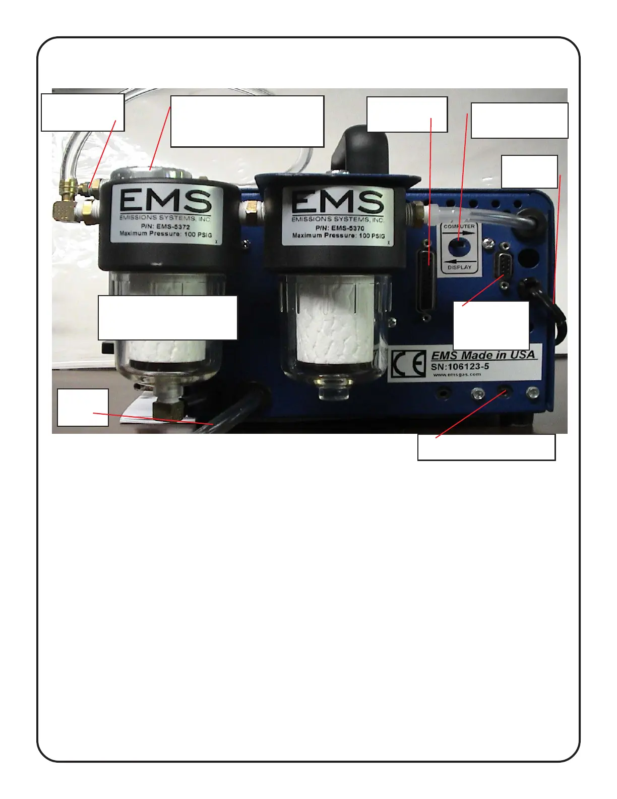
Figure 4 shows the view from the back of the analyzer. The specific details of each
item are described below, starting from the upper left corner of the analyzer and working clock-
wise. NOTE: The standard EMS filter arranegement has been changed and must be upgraded.
Sample Hose Connection: The sample hose connection uses a quick disconnect
coupler. This is helpful for storage of the analyzer and maintenance of the sample hose.
Display Control Switch: The display switch has two basic positions, Computer and
Display. The switch should normally be in the right position “Display”. If you are using
PC software for display or recording, the switch should be in the left position. Note: The
switch direction is based apon you looking at the display. The switch can be
changed any time during operation with out turning the power off.
DB9 Computer Connection: This is used to connect the analyzer to your PC/laptop or
for the wireless antenna.
Power Cord: Connect to the appropriate voltage supply source.
Sample Air Exhaust: The analyzer discharges the sample air out these ports. Do not
plug.
Printer Connection: Connect to an standard parallel printer.
Drain Hose: This hose will drain moisture collected during the sample process.
External Filter,Water Trap, Water Separator: This is the primary sample filter. Filter
maintenance will be discussed in the Maintenance section of this manual.
Figure 4
SAMPLE AIR EXHAUST
EXTERNAL
FILTER
WATER TRAP PRE-
FILTER W/ AUTOMATIC
DRAIN
SAMPLE
HOSE CONN.
HIGH PERFORMANCE
WATER/OIL SEPARATOR
WITH MANUAL DRAIN
PRINTER
CONN.
COMPUTER
MODE SWITCH
POWER
CORD
DB9
COMPUTER
CONN.
DRAIN
HOSE