PCD (Pitch Circle Diameter) / Bolt-Hole: Continued…
No. HOLE
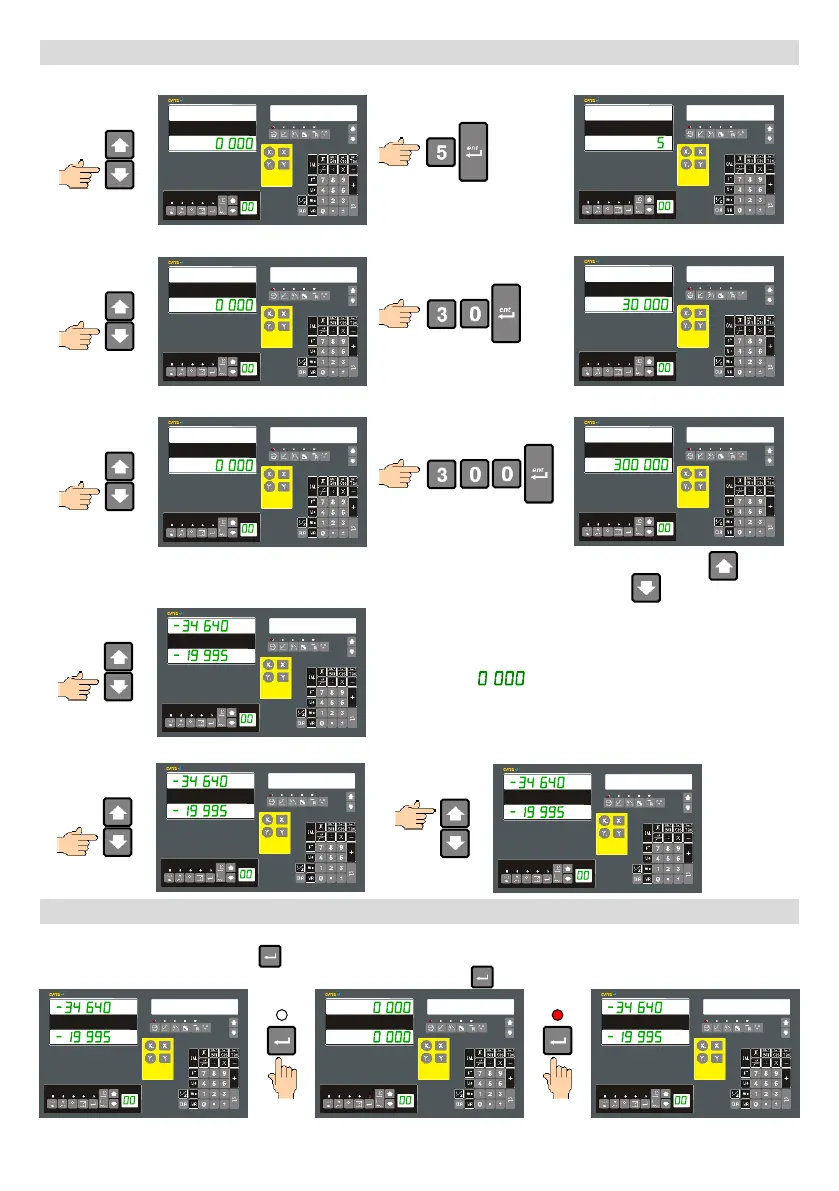
Move to Number of Holes entry and enter value.
No. HOLE
ST. ANG
Move to Start Angle entry and enter value.
ST. ANG
END ANG
Move to End Angle entry and enter value.
END ANG
Once all the parameters have been entered you can check them by going back through them using the
navigation key . Alternatively you can also start using the PCD immediately by pressing the key once more.
HOLE 1
The message window will show the current selected Hole
number and the X and Y-axis will show the offset to the
centre of that hole. By moving the axes until they are
both showing . you will now be at the calculated
hole centre.
Navigate between holes using the Message navigation keys.
HOLE 2
HOLE 1
Check ABS position whilst in PCD Function
If at any time whilst in the PCD function you would like to check the standard ABS position, relative to the workpiece
datum this can be done using the key. The PCD function is still active in the background. Once you have checked
the positions re-enter the PCD offset display by again pressing the key.
HOLE 1
HOLE 1
HOLE 1
- 22 -
 Loading...