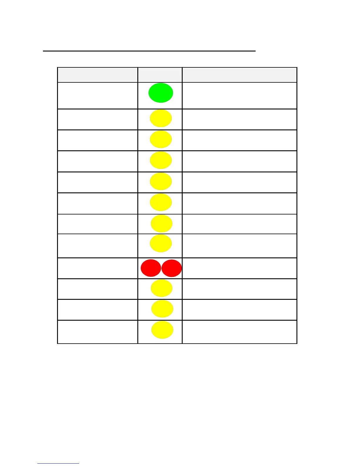
Control Panel Function
POWER
Indicates a good AC power supply.
ZONE FAULT
Illuminates, should one of the
detection devices, develop a fault
condition.
GENERAL FAULT
Illuminates, should a fault condition
occur within a Control Panel or device.
ARE / BRIGADE FAULT
Illuminates should a communication
fault occur between the Alarm Routing
equipment and the Control Panel.
EARTH FAULT
Illuminates should an earth fault
condition occur on the system.
ARE / BRIGADE
DISABLED
Illuminates when communication with
the Alarm Routing Equipment is
disabled
TEST MODE
Illuminates whilst a device or
detection zone is in “TEST MODE”.
SOUNDER & OUTPUTS
DISABLED
Illuminates when an individual
Sounder/Output device or sounder
zone is disabled.
FIRE
Illuminates when any device is in Fire
Alarm condition along with the fire
zonal LED.
SOUNDER FAULT
Illuminates should a Sounder Based
Device indicates a fault condition.
SYSTEM FAULT
Illuminates should a fault become
present with the control panel itself.
DETECTOR/ZONE
DISABLED
Illuminates when a Detection Device
or Zone is disabled.
Fig 3