Installation
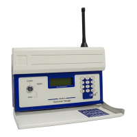
The Iris+ receiver consists of two sections, rstly the front casing which houses the receiver /
processor PCB and secondly the rear casing which houses the external connection PCB. The
installation of the Iris+ receiver requires the separation of the two sections and the xing of the
rear back box section to the wall. To complete the installation the front casing is then
re-assembled onto the rear back box. The following paragraphs outline the installation in a
step by step format;
1 Open lid 2 Remove retaining screws
4 Remove wing nuts
Remove the two circled
front retaining screws.
Remove the four
circled M4 wing nuts.
3 Open unit
Open the unit, by
lifting the display.
5 Remove front section
The front section of
the unit can now be
separated from the
back box.
1 2 3
4 5 6
7 8 9
0
MENU
SELECT
HELP
MENU
ESCAPE
CHARACTER
LEFT
CHARACTER
ENTER
CHARACTER
RIGHT
CURSOR
LEFT
CHARACTER
TEN RIGHT
CURSOR
RIGHT
MENU DOWN
/ DELETE
PIN ACCESS /
SPACE
MENU
UP / DONE
RADIO RX
AERIAL
TAMPER
TAMPER
ENG PORT
ENABLE
TX OV RX
ENG RS232
RXTX
NORMAL
OPERATION
END OF
BUS
ON
ALARM
RLY 1 RLY 2 RLY 3
SYSTEM
FAULT POWER
RESET
POWER
0V 12V
BATTERY
ON
JP9
USB
BUSY
USB-BOOT
NORMAL
PAGER
RX TX
AUX
RX TX
RS485
RX VALID TX
Iris II
ENG
PORT
0V
RX
TX
+3V3
3 WAY KEY
SWITCH
COMMON
POS 3
POS 2
POS 1
DISABLE
1.25A Fuse
RLY2
CON3
L1
BOX
TAMPER
1CON5
1CON4
IC1
IC2 IC3 IC4
Iris +12V OUT
INPUT 8
INPUT 7
INPUT 6
INPUT 5
INPUT 4
INPUT 3
INPUT 2
INPUT 1
OPTO 0V
Iris 0V OUT
0V
+12V
A
COM
B
A
COM
B
A
COM
B
N.O
COM
N.C
POWER
SUPPLY
RELAY
3
RELAY
2
RELAY
1
ALARM
RELAY
HARDWIRED INPUTS
CTS
RX
0V
DTR
TX
PAGER 232
OUT-
OUT+
IN-
IN+
A
B
A
B
+
-
RX
0V
TX
RS485
AUX
RS232
TAMPER
IN
TAMPER
OUT
REMOTE
BUZZER
6 Remove cable entry points
Remove the cable
entry blanking plates
shown, as necessary.
Be careful not to
damage the printed
circuit board within
the unit.
1.25A Fuse
RLY2
CON3
L1
BOX
TAMPER
1CON5
1CON4
IC1
IC2 IC3 IC4
Iris +12V OUT
INPUT 8
INPUT 7
INPUT 6
INPUT 5
INPUT 4
INPUT 3
INPUT 2
INPUT 1
OPTO 0V
Iris 0V OUT
0V
+12V
A
COM
B
A
COM
B
A
COM
B
N.O
COM
N.C
POWER
SUPPLY
RELAY
3
RELAY
2
RELAY
1
ALARM
RELAY
HARDWIRED INPUTS
CTS
RX
0V
DTR
TX
PAGER 232
OUT-
OUT+
IN-
IN+
A
B
A
B
+
-
RX
0V
TX
RS485
AUX
RS232
TAMPER
IN
TAMPER
OUT
REMOTE
BUZZER
1 2 3