35
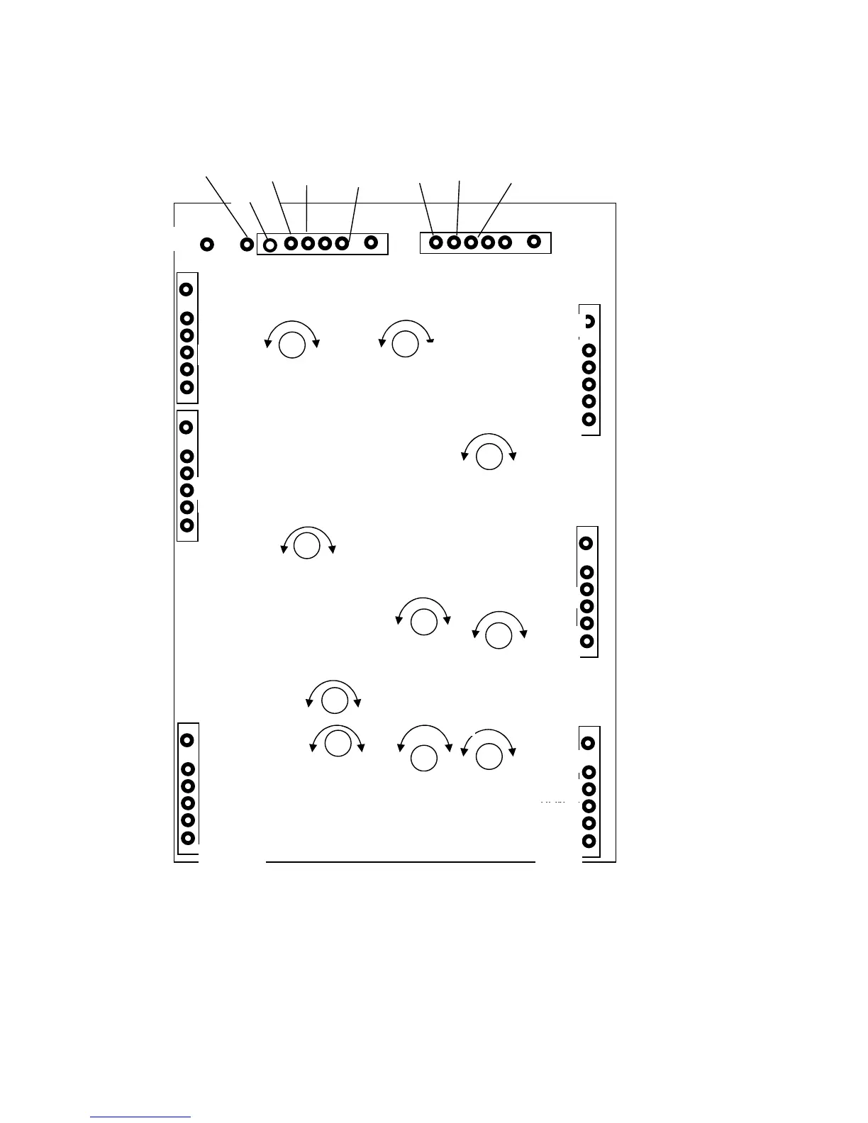
15.3 Control Board and Adjustment Points
The drawing below shows all the connections to the control board and the adjustment points.
Unless you know very well what you are doing and you have a reason to do it, do not modify any adjustment!
LEGEND:
GRY – grey GRN – green W – white V – violet Y – yellow PNK - pink
BLU – blue R – red BLK – black ORN - orange
Figure 17
RFIN
GREEN
YELLOW
YELLOW
YELLOW
GREEN
GRY/BLU
Ip
TP2
GRY/BLK
Y/GRN
RED
W
BLUE
ORN
ORN
ORN/BLK
Y/GRN
GRY
W/BLK
GRN
RED
X
ORN/BLK
X
WHT/BLK
VIOLET
WHITE
Sensitivity
+
-
+ Ip
-
+
Ip
EG2
+V
Eg2
Ig2Lim
+Ig2
Ig2
Sensitivity
IPTRIP
IpTRIP
+
Ip
IPDispl
V
Ip
+ Ip
BIAS2
+Ip
EBS
On
10VAC1
T110
RFIN
BS2
BS1
READY
BIAS
O/D
DISP
+5V
IG2R
EG2
GND
OD/TX
FAULT
SWR/FLT
GND
 Loading...