- -
9
6. PRECAUTION FOR OPERATION
Check all parts for proper condition before operation; if normal safety precautions are notice
carefully, this machine can provide you withstanding of accurate service.
(1) Before Operation
(a) Fill the lubricant.
(b) In order to keep the accurate precision, the table must be free from dust and oil deposits.
(c) Check to see that the tools are correctly set and the work-piece is set firmly.
(d) Be sure the speed is not set too fast.
(e) Be sure everything is ready before use.
(2) After Operation
(a) Turn off the electric switch.
(b) Turn down the tools.
(c) Clean the machine and coat it with lubricant.
(d) Cover the machine with cloth to keep out the dust.
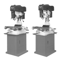
(3) Adjustment of Head
(a) To raise and lower the head, loosen the two heavy duty head lock nuts shown in Fig.l. Use the
left side head handle to raise and lower the head on its rack and pinion mechanism. When the
desired height is reached, tighten the bolts to avoid vibration.
(b) Head may be rotated 360∘by loosening the same bolts mentioned above. Adjust the head to
the desired angle, then fix the heavy duty head lock-nuts. It is tighten the same time to fix the
head if drilling & milling too much.
(4) Preparing for Drilling (see fig. 2)(Except addition power feed system).
Turn of the knob make loose the taper body of worm gear and spring base. Then we decide
spindle stroke setting the positive depth stop gauge for drilling blind hole or free state for pass
hole.
(5) Preparing for Milling (see fig. 2)(Except addition power feed system).
(a) Adjust the positive depth stop gauge to highest point position.
(b) Turn tight of the knob be use to taper friction force coupling the worm gear and spring base.
Then turning the handle wheel by micro set the spindle of work piece machining height.
(c) Lock the rack sleeve at the desired height with fixed bolt.