Page 5
electrIcal requIrementS
IMPORTANT
: Fill the
fitness system
with water before turning on the power.
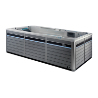
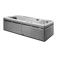
Your ENDLESS POOLS
fitness system
has been carefully designed to
give you maximum safety against electrical shock. Connecting the
fitness
system
to an improperly wired circuit will negate many of the
fitness
system
’s safety features. Improper wiring may also cause electrocution,
risk of fire, and other risks of injuries. Please read and follow the electrical
installation requirements and instructions completely!
230 VOLT PERMANENTLY CONNECTED
ENDLESS POOLS
fitness system
s must be wired in accordance with all
applicable local electrical codes. All electrical work should be done by an
experienced, licensed electrician. We recommend the use of appropriate
electrical conduit, fittings, and wire for all circuits.
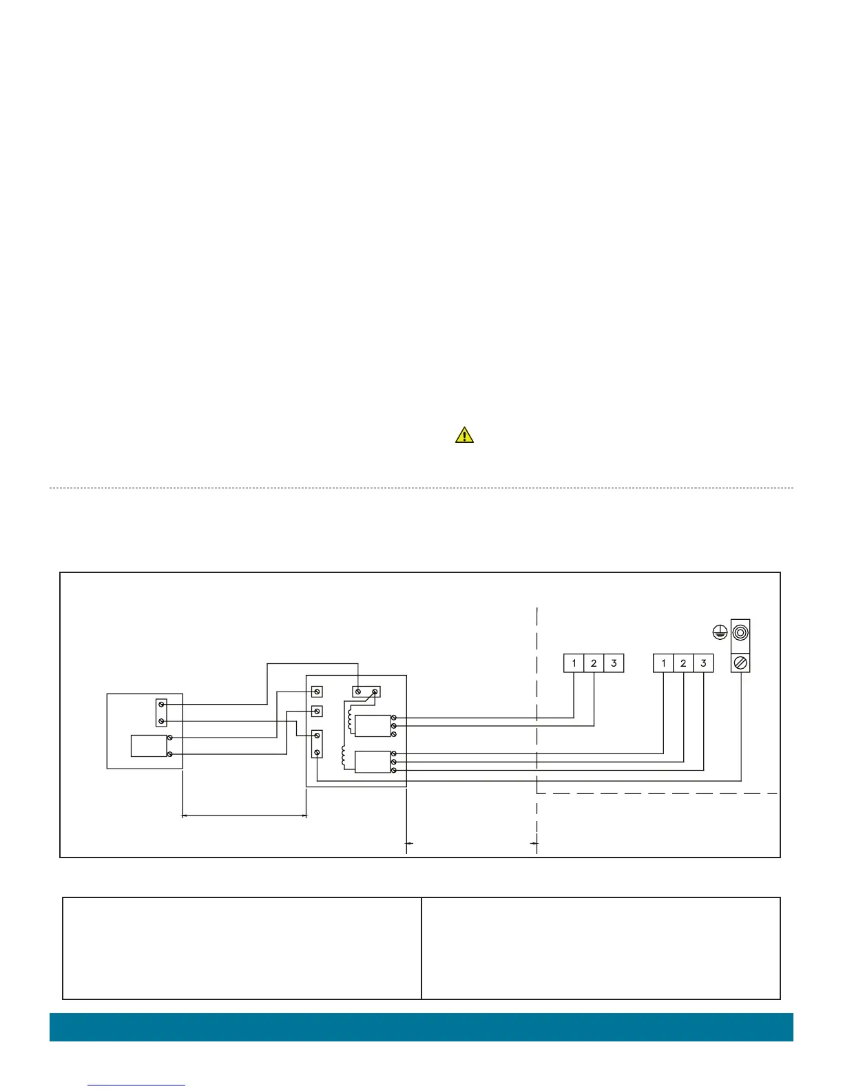
The diagram below illustrates how to wire the
fitness system
model:
• An electrical subpanel containing two 30 Amp breakers is included with
your
fitness system
. We recommend that this subpanel be used to supply
power to the
fitness system
.
• The subpanel requires a 60 amp, single phase, 230 volt, four wire service
(two line, one neutral, one ground). The grounding conductor must not be
less than #6 AWG. Refer to local codes and to NEC 250-122 (table).
• Mount the subpanel in the vicinity of the
fitness system
, but not closer
than five
feet away, in accordance with all local codes. (N.E.C. 680-38 to
41-A-3)
• Open
fitness system
by removing the 4 screws holding the vertical
T-spacer located in the center of the equipment compartment (back
side of
fitness system
). Slide panel towards center, raise panel, pull
bottom out, lower, disconnect light wires on both side and remove,
repeat for other panel.
• Insert power wires into
fitness system
from either side towards the
bottom, you will find a plastic cap attached to wall.
• Once your
fitness system
has been filled with water, turn it on
and test all of the circuit breakers.
IMPORTANT: If breakers immediately trip, verify that the wires are
correctly connected. Breaker should be tested prior to each use. Here’s
how:
1. Push the “TEST” button on each GFCI breaker, and observe it
click OFF.
2. Wait 30 seconds, then push the breaker switch to the OFF (down)
position (to ensure that it has completely disengaged), then push
the breaker switch to the ON (up) position. If you don't wait 30
seconds, the
fitness system
’s power indicator may continue to
blink – try again.
If any of the GFCI breakers fails to operate in this manner, your
fitness
system
may have an electrical malfunction, and you may be at risk of
electrical shock. Turn off all circuits and do not use the
fitness system
until the problem has been corrected by an authorized service agent.
WARNING: Removing, or bypassing any GFCI breaker will result
in an unsafe
fitness system
and will void the
fitness system
’s
warranty.
IMPORTANT: If you ever need to move or relocate your ENDLESS POOLS fitness system, it is essential that you understand and apply these
installation requirements. Your ENDLESS POOLS fitness system has been carefully engineered to provide maximum safety against electric shock.
Remember, connecting the fitness system to an improperly wired circuit will negate many of its safety features.
NOTE: Long wiring runs may require larger-gauge wire than stated.
CAUTIONS
USE COPPER CONDUCTORS ONLY.
USE SUPPLY WIRES SUITABLE FOR 75°C/167°F.
DISCONNECT ALL SUPPLY CONNECTIONS BEFORE SERVICING.
CONNECT ONLY TO A CIRCUIT PROTECTED BY A CLASS A
GROUND-FAULT INTERRUPTER.
THESE FITNESS SYSTEMS ARE INTENDED FOR USE WITH GFCI
SUBPANEL PROVIDED.
INCORRECT WIRING WILL DAMAGE CIRCUIT BOARDS.
REFER TO THE WIRING INSTRUCTIONS INCLUDED WITH THE
SUB-PANEL FOR DETAILED WIRING INSTRUCTIONS.
Electrical Requirements
230 VAC, 48A, 60Hz,
(FIELD WIRING)
230 VAC, 60 Amp
2-POLE
CIRCUIT BREAKER
(NON GFCI)
MAIN SERVICE
ELECTRICAL
PANEL
SUB-PANEL
WITH GFCI
BREAKERS
P/N 304130
MORE THAN 5 FEET
THE SUB-PANEL MUST BE
WITHIN SIGHT OF THE SPA
DO NOT EXCEED 50 FEET
LESS THAN 100 FT.
FITNESS SYSTEM JUNCTION BOX
L2, HOT, #10 AWG RED
MAIN INPUT
#6 AWG WHITE, NEUTRAL
#6 AWG GREEN, GROUND
#6 AWG BLUE, L1
#6 AWG RED, L2
L1
L2
GRD
60A
30A
30A
N
1
2
L1, HOT, #10 AWG BLUE
L2, HOT, #10 AWG RED
L1, HOT, #10 AWG BLUE
N, NEUTRAL, #10 AWG WHITE
GROUND, #6 AWG GREEN
CIRCUIT 1
CIRCUIT 2
GRN