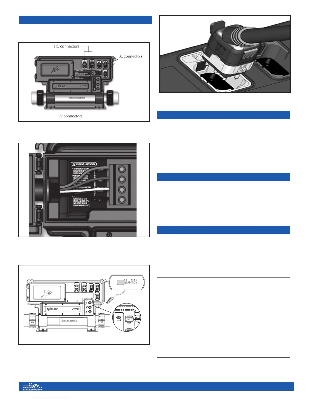
HEATER CONTROLLER
Connections simply snap into appropriate color coded receptacles.
TYPICAL SETTINGS
Set Point : 59°F to 104°F / Factory set at 84°F
Filter Cycle Duration: 0 to 24 hrs / Factory set at 24 hrs
Jet Pump Run Time: 1 to 255 min. / Factory set at 30 min.
Light Timeout: 1 to 255 min. / Factory set at 120 min.
Max Set Point: 59°F to 104°F / Factory set at 104°F
Purge Cycle Frequency: 1 to 4 times a day / Factory set at 4
KEYPAD DOESN’T SEEM TO WORK
If a keypad doesn’t seem to work:
• Verify keypad connections.
• Replace keypad if problem is corrected.
• Replace in.xe if problem is not corrected.
in.xe UL/CSA electrical specifications:
Input rating: 120/240 VAC
(2-phase required, with neutral) 48 A maximum, 60Hz.
Software limited to 24A. Install on a 30A GFCI circuit.
Output ratings:
Output Voltage Current Typical Device
Out 1 120/240V 17FLA Pump 1
Out 3 120/240V 0.8 A Circulation
Pump/Blower
Out 4 120/240V 1 A Ozone Generator
Out 5 120/240V 5 A Audio/Video device
L1 Light, 12VAC, 0.1 A
CO Communications port *
C1 Top side controller *
*CO: Comm.connector (in.stik).
Keypad connection
Input wiring shown above
8
SS Assembly 5-09 5/28/09 8:19 AM Page 10