Oil Leak Detector NAR 300 system
32 Endress+Hauser
8.3 Alarm other than Oil leak detection or Fail safe (breaking, freezing)
Note!
When performing the following work, please be sure to consult a service person from
Endress+Hauser.
8.3.1 Segmentation of trouble spot
In case of the IS construction system:
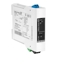
Please measure the voltage between "Sensor Input" + and - terminal in the Transmitter NRR 262
using Tester.
In case of the Explosion-proof construction system:
Please measure the voltage between " TB-1"H+ and H- terminal in the Sensor I/F Ex box using Tes-
ter.
Condition Countermeasure
0±0.5 V : without system
power
• There is not the power supply for the sensor.
• There is the cause of false alarm in the transmitter or upper alarm
system side.
*In case of IS construction, it is the same problem if the wiring
between a transmitter NRR 262 and a Sensor I/F Ex box shorts out.
• Please check the LED luminescent color on the transmitter.
• Please proceed to the next section "8.3.2 Problem between
Transmitter and Alarm system"
17.5±0.5 V: normal alarm
condition
• Alarm signal is input on the transmitter.
• There is the cause for false alarm in a lower detection system from
the board of the Sensor I/F Ex box to the float sensor.
• Please proceed to the next section "8.3.3 Problem between Sensor
I/F Ex box board and Sensor problem"
20.7±0.5 V: Voltage when
the empty pit
• The detection signal for empty pit is input on the transmitter.
• The false alarm is generated by the transmitter.
• Please replace the transmitter.
23.2±0.5 V: the breaking
between Transmitter NRR
262 and Sensor I/F Ex box
• The voltage of condition which there is no electrical load on system is
detected.
• Please check a electrical continuity of the transmitter NRR 262 and a
Sensor I/F Ex box.
8 Troubleshooting
 Loading...