Do you have a question about the Endress+Hauser Nivotester FTL325P and is the answer not in the manual?
Explains the purpose of the Operating Instructions and its scope.
Defines safety, electrical, and information symbols used throughout the manual.
Lists and describes additional documentation relevant to the device and its applications.
Outlines the qualifications, authorization, and familiarity required for personnel.
Specifies the intended applications and limitations for the Nivotester product.
Provides general safety precautions for working with and around the device.
Details measures to ensure safe operation and prevent potential hazards.
Covers product safety compliance, including CE and EAC conformity marks.
Offers guidance on implementing IT security measures for device data transfer.
Steps for checking the device upon delivery to ensure it is correct and undamaged.
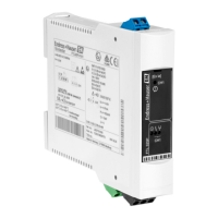
Methods for identifying the device using its nameplate and online tools.
Guidelines for proper storage conditions and transportation of the device.
Specifies the environmental and physical conditions required for device installation.
Detailed instructions for physically mounting the device, including orientation.
Procedures to verify correct installation and initial setup.
Safety and regulatory requirements that must be met before electrical connections.
Step-by-step guide for wiring the device to power and signal circuits.
Illustrates the layout and function of the device's terminal connections.
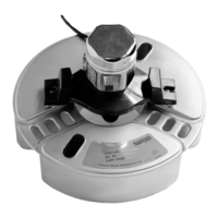
Instructions for connecting various types of sensors to the device.
Guidance on integrating the device with signal and control system wiring.
Specific instructions for connecting the device to its power supply.
Provides specific wiring configurations for advanced or specialized setups.
Information regarding the device's environmental protection ratings (IP/IK).
Final verification steps after all electrical connections have been made.
Overview of the device's operational philosophy and configuration methods.
Procedure for safely opening the front panel to access controls.
Explanation of the device's indicators, including LEDs and their states.
Description of the physical controls such as buttons and switches on the device.
Steps to verify proper installation and device functionality before use.
Configuration of device operational parameters using DIP switches and mode settings.
Details on setting switches on the electronic insert for various sensor inputs.
Troubleshooting steps for when the device fails to switch or operate correctly.
Addressing issues where the device switches at the wrong times or conditions.
Diagnosing and resolving persistent fault indicator signals.
Troubleshooting device behavior after a power interruption or restart.
Provides an overview of the repair concept and general repair procedures.
Specific safety guidelines for repairing devices used in hazardous areas.
Information on how to identify and order necessary replacement parts.
Procedures and conditions for returning devices to Endress+Hauser.
Instructions for the environmentally responsible disposal of the device according to WEEE.
Details on an optional protective housing accessory for enhanced environmental protection.
Specifies the acceptable voltage ranges for AC and DC power supply.
Details the power consumption values for both AC and DC operation.
Describes the characteristics of the device's relay outputs, including switching capacity.
Specifies the operating and storage temperature limits for the device.
| Brand | Endress+Hauser |
|---|---|
| Model | Nivotester FTL325P |
| Category | Security Sensors |
| Language | English |