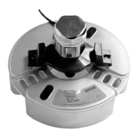
Oil Leak Detector NAR 300 system
34 Endress+Hauser
8.3.3 Problem between Sensor I/F Ex box and Sensor
Each independent signal sent from sensors of conductivity and tuning-fork is combined in Sensor
I/F Ex box board and are recognized as a oil leak alarm for the first time.
In consequence, when the setting condition and detection output logic for each sensors are not
consistent with each other, it is the failure of complete sensor unit.
Note!
Before checking the false alarm of the Float Sensor NAR 300, please make sure the condition is not
in oil leak detection or fail safe.
Please make sure to remove the oil film on electrode of conductivity sensor and the trash in tuning-
fork sensor.
1. Remove the board guard after removing the cover of transmitter NRR 261 (IS terminal box) or
Sensor I/F Ex box.
2. When the conductivity and tuning-fork sensors are movable, measure the direct voltage.
Conductivity sensor Two terminals on backside of board: GND5 brown, ADJ yellow
For example:
When detecting oil or air : 1.0±0.3V
When detecting water: 5.0±0.3V
Two terminals on backside of board: GND5 brown, REF blue
Conductive threshold: 1.5±0.3V
*Refer to the below fig.15 "IS terminal box "
Note!
When bordering on the conductive threshold, when it is lower, oil or air
are detected.When it is upper, water is detected.
Tuning-fork sensor Between board terminal FEL+ and FEL-
When detecting the liquid: 6.3±0.5V
When detecting the empty pit: 8.3±0.5V
When breaking of cable: 9.4±0.5V
*Refer to "6. Electrical connection, IS terminal diagram"
GND5
Brown
REF
Blue
ADJ
Yellow
Terminal NRR 261
Ex box
8 Troubleshooting

 Loading...