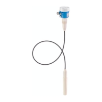
The Nivocompact FTC 831 is a capacitive level limit switch designed for limit detection in silos containing bulk solids, suitable for both minimum and maximum level indication. It is also approved for use in the food processing industry and is typically mounted from above in silos.
Function Description
The device operates on the principle of a discharge circuit. A metal plate at the end of the probe, alongside the insulation and the surrounding silo wall (or bulk solid), forms two electrodes of a capacitor. The capacitance of this capacitor (C_s) is formed by the probe and its surroundings. The limit value is based on the principle of a discharge circuit.
When the probe is in air (or a material with a dielectric constant of ε_r = 1), the discharge time constant is C_s. If a material with a dielectric constant ε_r ≥ 2.0 moves into the high-frequency electrical field at the end of the probe, the capacitance C_a increases, and with it, the time constant. This change in the time constant is evaluated, and the Nivocompact FTC 831 is activated, according to its switching mode.
The Nivocompact FTC 831 features a built-in mechanism for minimum/maximum fail-safe switching, ensuring high operational safety.
- Maximum Fail-Safe: The circuit is blocked if the probe is covered or the power supply fails.
- Minimum Fail-Safe: The circuit is blocked if the probe is uncovered or the power supply fails.
A red LED on the electronic insert indicates the switching status.
Important Technical Specifications
- Operating Temperature in Silo: -20 °C to +60 °C
- Operating Pressure in Silo: Up to 6 bar
- Max. Permissible Load on Probe: 2500 N vertical
- Grain Size of Bulk Solid: Up to approx. 10 mm
- Minimum Dielectric Constant of Material: 2.0 (factory-set, no adjustment required). Minimum adjustment of dielectric constant ε_r for bulk solid: 1.6.
- Ambient Temperature for Housing: -20 °C to +60 °C
- Storage Temperature: -40 °C to +85 °C
- Construction: Rope probe with electronics at end of probe.
- Process Connection: Parallel thread G 1 1/2 A according to DIN ISO 228/I.
- Process Connection Material: Glass-fibre reinforced polyester (PBTP).
- Probe Material: Reinforced steel wire mesh and electronics with PE coating.
- Insulation from Material: Fully insulated.
Probe Length Tolerances:
- Up to 1 m: +0 mm, -5 mm
- Up to 3 m: +0 mm, -10 mm
- Up to 6 m: +0 mm, -20 mm
- Up to 20 m: +0 mm, -30 mm
Housing Versions:
- Aluminium housing, IP 55
- Aluminium housing, IP 66
- Aluminium housing with synthetic coating, IP 66
- Synthetic housing in PBTP, IP 66 (Protection IP... acc. to DIN 40050)
Cable Gland:
- Housing IP 55: standard PG in nickel-plated brass with NBR gasket for cable diameter 7...10 mm.
- Housing IP 66: water-tight PG in polyamide with Neoprene-CR gasket for cable diameter 5...12 mm.
Electronic Inserts:
- Terminal Connections: For max. 2.5 mm².
- Measuring Frequency: Approx. 1.6 MHz.
- Switching Delay: Approx. 0.5 s...approx. 20 s, selectable.
- Minimum/Maximum Fail-Safe Switching: Selectable with rotary switch.
- Switching Indication: Red LED.
Electronic Insert EC 40 (Two-Wire Connection) for AC:
- Power Supply U~: 21 V...250 V, 50/60 Hz.
- Connected Loads, Short-Term (max. 40 ms): Max. 1.5 A; max. 375 VA at 250 V; max. 36 VA at 24 V.
- Maximum Voltage Drop: 11 V.
- Connected Loads, Continuous: Max. 350 mA; max. 87 VA at 250 V; max. 8.4 VA at 24 V.
- Minimum Load Current at 250 V: 10 mA (2.5 VA).
- Minimum Load Current at 24 V: 20 mA (0.5 VA).
- No-Load Current (rms): < 5 mA.
Electronic Inserts EC 42 (Three-Wire PNP) for DC:
- Power Supply U=: 10 V...55 V.
- Superimposed AC Voltage Upp: Max. 5 V.
- Current Consumption: Max. 15 mA.
- Load Connection: Open collector, PNP (EC 42) or NPN (EC 43).
- Switching Voltage: Max. 55 V.
- Connected Load, Short-Term (max. 1 s): Max. 1 A.
- Connected Load, Continuous: Max. 350 mA.
- Residual Current with Transistor Blocked: < 100 µA.
- Protected Against Reverse Polarity.
Electronic Insert EC 44 (Relay Output) for DC and AC:
- Power Supply U=: 20 V...200 V or U~: 21 V...250 V, 50/60 Hz.
- Current Consumption (rms): Max. 5 mA.
- Peak Inrush Current: Max. 200 mA, max. 5 ms.
- Pulse Current: Max. 50 mA, max. 5 ms.
- Pulse Frequency: Approx. 1.5 s.
- Output: Potential-free change-over contact.
- Contact Load Capacity:
- U~ max. 250 V, I~ max. 6 A, P~ max. 1500 VA (cos φ = 1) or P~ max. 750 VA, (cos φ ≥ 0.7).
- U= max. 250 V, I= max. 6 A, P= max. 200 W.
- Operating Life: Min. 10⁵ switchings at max. contact load.
- Additional Switching Delay: Max. 1.5 s.
EMC:
- Interference Emission to EN 61326, Electrical Equipment Class A.
- Interference Immunity to EN 61326.
- EMC Test Procedures to TI 241F/00/en.
Usage Features
Project Planning and Installation:
- The Nivocompact FTC 831 can be installed in silos made of different materials (e.g., metal, plastic, concrete).
- Installation Point: Note the angle of material flow or the outlet funnel when determining the measuring point. The Nivocompact switches (also with bulk solids with very small dielectric constants) when the probe end is covered by a few centimetres of material or when the material drops a few centimetres below the probe end. The filling curtain should not be directed onto the probe.
- Minimum Distance: A minimum distance of 500 mm between the probe ends of two Nivocompact FTC 831 instruments must be maintained to ensure no mutual interference. This also applies to all FTC 831 probes mounted next to one another in silos with non-conducting walls. The distance from the probe end of an FTC 831 to the probe end of an FTC 731 must also be at least 500 mm. The distance from the probe end of a Nivocompact FTC 831 to the silo wall or to any material build-up must be at least 200 mm.
- Resistance to Load: With minimum detection, take note of the maximum load of the rope and the strength of the silo roof. Very high tensile forces may occur at the material outlet, especially with heavy powdery bulk materials which tend to form build-up. These forces are significantly greater in the middle of the silo over the material discharge point than at the silo walls.
- Installation in the Open: A protective sun cover is available as an accessory to protect the Nivocompact with the aluminium housing from excessive temperature and from condensation which may form in the housing due to large temperature variations.
Mounting:
- Tools required: Open-end spanner 60 AF, screwdriver (blade width 5...6 mm or Phillips PZD 2).
- Ensure the probe length is correct for the installation point and application. The probe can be shortened if too long.
- Place the elastomer/fibre gasket against the sealing surface of the Nivocompact (do not apply sealing material around the thread).
- Straighten out the cable at the lower end and feed it carefully through the threaded boss, ensuring insulation is not damaged.
- When screwing in the Nivocompact, turn the instrument by the 60 AF nut only. If the instrument does not turn easily, slightly cut into the thread of the boss.
- A torque of 80 Nm...100 Nm is sufficient for a reliable seal up to 6 bar. A torque over 120 Nm will destroy the plastic thread.
Rotating the Housing:
- The housing can be rotated 360° if the cable gland is facing in the wrong direction after the Nivocompact has been securely screwed in.
- Loosening: Unscrew and remove the housing cover. Loosen the central screw in the electronic insert. Remove the plug-in electronic insert from the housing using the handle. Slightly loosen the 3 screws in the housing.
- Tightening: Tighten the 3 screws in the housing for a good seal. Insert the electronic insert in the plug. Securely tighten the central mounting screw, ensuring the cable gland remains free.
Wiring Connection:
- The type of electronic insert (EC 40, EC 42, EC 43, EC 44) is identified by the last number of the order code on the nameplate.
- Load Limit Values: Note the limit values of the loads to prevent damage to the electronic insert or relay contact.
- Fuse: Ensure the rating of the fine-wire fuse corresponds to the maximum load. The fine-wire fuse does not protect the electronic insert.
- Diameter of Wiring: Low-cost cabling with diameters of 0.5 mm² to max. 1.5 mm² is recommended due to small current usage.
- Earth Connection, Grounding: The Nivocompact must be grounded for reliable, interference-free operation. This can be achieved by connecting it to a grounded silo (metal or reinforced concrete) or to the earth conductor PE. The probe requires a good counter potential, achieved by connecting the ground connection on the outside of the housing to an electrically conductive part of the silo. If the silo is non-conductive, connect conductive and grounded components near the silo to the ground connection. The connecting cable should be as short as possible.
Wiring On-Site:
- Tools required: Open-end spanner 22 AF, screwdrivers (blade width approx. 4 mm and 7 mm or Phillips PZD 1 and PZD 2), common electrical tools.
- Before connecting, ensure the power supply matches the specification on the nameplate.
- Connect according to the appropriate diagram (Fig. 10 to Fig. 13).
- Prevent water from entering the housing during connection.
- The standard cable gland gasket is for cable diameters 7 mm to 10 mm. Use a suitable gasket for other diameters.
- The "water-tight" cable gland can seal cables with diameters from 5 mm to 12 mm.
- Ensure a good short ground connection from the housing to the silo or grounded metal parts nearby.
- Screw in the cable gland securely to comply with IP 55 or IP 66 protection.
- For open or moist surroundings, sealing the standard cable gland with sealing compound is recommended (not required with "water-tight" cable gland).
Calibration:
- Tools required: Screwdriver with blade width approx. 3 mm and 4 mm.
- The rotary switches and adjusting elements for calibration are on the electronic insert in the housing. Direct contact with these elements is possible with voltages up to 250 V. Use a screwdriver with insulation as far as the blade only or use tape over the terminals with insulating tape before calibration.
- Turn on the power supply.
- Switching Delay: Set the switching delay between approx. 0.5 s and 20 s. Select the optimum time for the application.
- Scalar Calibration: Only approximate, as the function is not entirely linear. Exact calibration is possible by touching the uncovered probe (connection and calibration in the factory).
- Capacitance Calibration (Changing Factory-Set Adjustment):
- May be necessary if the dielectric constant (ε_r) of the material is smaller than 2.0 (e.g., plastic granulate), or if minimum distances cannot be maintained. Calibration is possible for ε_r > 1.6.
- For this calibration, the silo must be empty or the level at least 100 mm below the probe.
- The adjuster for calibration is approx. 30 turns from one end of the range to the other.
- Initial Settings: Switch on power supply. Set to maximum fail-safe mode. Turn the adjuster for switching delay counterclockwise until it reaches the stop. If necessary, turn the adjuster for capacitance calibration clockwise until the LED is off.
- Determining the Switching Point: Turn the adjuster for capacitance calibration counterclockwise until the LED lights up. Then turn the adjuster for capacitance calibration clockwise until the LED goes out. Then turn the adjuster for capacitance calibration clockwise through the specified number of turns based on material characteristics (very low, low, average, high dielectric constant).
- Adjusting for Material Characteristics: When the probe is covered with non-conductive bulk solid having a low dielectric constant, the Nivocompact only switches when the rod is submerged by several centimetres. The degree of covering depends on the calibration. Turning the fine calibrating element clockwise causes the Nivocompact to become less sensitive.
- Do Not Forget! Adjust the switching delay (refer to Page 19). Select the safety switching required (refer to Page 20).
Maintenance Features
Function Control:
- Check for correct operation of limit detection by increasing and decreasing the level in the silo at roughly the same height as the probe end.
Final Points:
- Screw the housing cover securely down after connection and calibration to comply with IP 55 or IP 66 standards.
- For applications in the open, a protective sun cover (accessory) should be used to cover the aluminium housing of the Nivocompact.
Maintenance:
- The capacitive level limit switch Nivocompact FTC 831 requires no maintenance when correctly installed and used properly under the normal conditions specified by the system.
- When cleaning and checking the silo: Examine the probe for damage, especially to the cable. Remove any material build-up on the end of the probe.
- With initial but permanently low material build-up: Carry out another capacitance calibration after the material build-up if the Nivocompact does not switch correctly.
- Ensure that the cable gland and housing cover are tight fitting so that no moisture can enter.
Troubleshooting:
- When an error is indicated, first check:
- The Nivocompact is properly connected.
- Earthing and ground connection are correct.
- A power supply exists at the terminals.
- All instruments connected are operating correctly.
- In the case of the electronic insert EC 40, the minimum required load of the connected instruments is at least present.
- The correct fail-safe mode has been chosen.
- The switching delay has been correctly set.
- The capacitance calibration has been carried out correctly.
- Carry out a function control (see "Calibration").
- Refer to the Error Tables (Fig. 20 and Fig. 21) for specific troubleshooting steps based on maximum or minimum fail-safe mode, probe status (free/covered), electronic switch status (blocked/connected), and LED indication (on/off). Possible causes include high material build-up, water in housing, dielectric constant too small, different material used than calibrated for, drier material used than calibrated for, cable damaged, or probe end touching silo wall/residual material.
Replacement of Parts:
- Replacing the Electronic Insert: Switch off all power. Remove electrical connections. Loosen central screw. Lift out insert. Push new insert into plug. Tighten central screw. Connect wires. Switch on power. Carry out new capacitance calibration with an empty silo. Set switching delay. Select same fail-safe mode. Check operation.
- Replacing the Probe: Remove, install, and connect as described for shortening the cable. Carry out new capacitance calibration with an empty silo. Check operation.
Returning Parts for Repair:
- If the Nivocompact FTC 831 cannot be repaired and needs to be returned to Endress+Hauser, remove all material residue from the probe, especially if dangerous (corrosive, poisonous, carcinogenic, radioactive). Return parts only after thorough cleaning. Check for scratches and diffusion through plastic material.
- When returning, state the exact material used and its characteristics, and provide a brief description of the error to help diagnose the reason and reduce costs.
Shortening the Cable:
- Tools required: Open-end spanner 17 AF, screwdriver (blade width 5...6 mm or Phillips PZD 2), universal pliers, wire cutters, wire stripper.
- Taking Apart: Unscrew and remove housing cover. Take out spare plug connectors. Unscrew central screw in electronic insert. Lift out electronic insert. Remove plug base for electronic insert. Cut off plug connector from probe cable cores. Remove plug connector with rest of probe cable. Unscrew 3 screws in housing. Remove sealing screw at hexagonal nut. Loosen terminal clamps. Push cable up from below. Terminal clamps will come out at the top.
- Shortening: Push cable upwards to correct cable length. Cut off cable about 150 mm above hexagonal nut (universal pliers/wire cutter). Leave approx. 140 mm of core free. Remove cable sheath (external insulation) with knife. Carefully cut round steel armouring wire at a time with wire cutter. Remove approx. 140 mm of internal cable sheath.
- Assembling: Put terminal clamps around cable and place in cone tightly. The cable and its armouring should protrude approx. 5 mm above terminal clamps. Push sealing washers into cone. Screw sealing screw into cone tip tightly. Put black gasket on hexagonal nut. Put screw guide ring in cone. Thread 4 free cores from below through rubber bush. Tighten housing onto hexagonal nut using 3 screws. Make sure hexagonal screws are tightened up so that housing is watertight.
- Connection: Put 4 free cores into connector supplied, ensuring colours correspond. Crimp plug connector together. Cut off remaining core ends. Plug connector on end of probe cable into connector on end of plug base. Recheck core colours. Plug plug base for electronic insert with mounting on central threaded rod in housing. Plug base should lie approximately opposite ground screw. Put plug connector and cores at bottom of housing. Plug electronic insert into plug base and secure with central screw, ensuring cable gland is free. Screw on housing cover.