Do you have a question about the Endress+Hauser Liquiphant FTL51B and is the answer not in the manual?
Alerts to dangerous situations and potential injuries.
Represents electrical connections and grounding.
Indicates permitted actions, forbidden actions, and tips.
Denotes items, views, and hazardous/safe areas in diagrams.
Specifies qualifications and authorizations for personnel.
Defines the intended application and limitations of the device.
Outlines necessary protective equipment and regulations.
Covers device condition, operator responsibility, and modifications.
Confirms design, testing, and compliance with standards and directives.
Highlights the need for user-implemented security measures for data transfer.
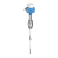
Details the physical components and structure of the Liquiphant FTL51B.
Steps to verify goods upon delivery for damage and accuracy.
Explains how to identify the device using nameplate or digital tools.
Specifies information found on the device's nameplate.
Provides the address of the manufacturing plant.
Guidelines for storing and handling the device to prevent damage.
Factors to consider for optimal device placement and orientation.
How to set the switch point based on liquid level and orientation.
How liquid viscosity affects tuning fork positioning and performance.
Installation techniques to prevent material buildup on the sensor.
Ensuring sufficient space for mounting and connections.
Guidelines for supporting the device under dynamic load conditions.
Instructions for installing the weld-in adapter with a leakage hole.
Procedures and considerations for physically installing the measuring device.
Lists the tools needed for sensor installation and electrical connection.
Steps for aligning the cable entry by adjusting the housing.
Information on sliding sleeves for proper sensor positioning.
Checklist for verifying correct installation and connections.
Prerequisites for connecting the device, including hazardous area requirements.
Guidelines for connecting the protective earth conductor for safety.
General procedures for connecting the device to power and output.
Wiring details for the 2-wire AC electronic insert.
Wiring details for the 3-wire DC-PNP electronic insert.
Wiring for devices with universal current connection and relay output.
Wiring for DC connection with relay output.
Connection details for PFM output signal transmission.
Wiring for 2-wire NAMUR signal transmission.
Optional module for wireless communication and diagnostics.
Optional module for visual status indication.
Procedures for installing the cable gland and ensuring proper entry.
Checklist to verify wiring integrity and correct setup.
Introduction to various methods for operating and monitoring the device.
Describes interaction via buttons, DIP switches, and optional modules.
Step-by-step guide to perform a functional test using the electronic insert button.
Performing a functional test using an external test magnet.
Utilizing Bluetooth for device diagnostics, verification, and monitoring.
Verifying post-installation and post-connection checks before operation.
Describes device output behavior during power-up.
Steps and requirements for connecting via the SmartBlue mobile application.
Accessing device status and event logs via the app.
Navigating menus for operating mode and density settings.
Accessing device information like serial number and firmware version.
Performing verification tests to ensure device status and generate reports.
Requirements for periodic testing of safety-related devices.
Interpreting LED indicators for device status and faults.
Troubleshooting device issues using the SmartBlue app.
General guidance on device upkeep and necessary tasks.
Instructions on how to clean the device safely and effectively.
Overview of the Endress+Hauser repair concept and modular design.
Safety precautions and requirements for repairing Ex-certified devices.
How to identify and order replacement parts for the device.
Process and conditions for returning devices to the manufacturer.
Information on proper disposal of the device according to WEEE directive.
List of accessories designed for specific use with the device.
An accessory used for performing functional tests on the device.
Covers to protect the device from environmental factors.
Various types of M12 plug-in jacks for connections.
Modules like Bluetooth or LED requiring a tall housing cover.
Sleeves for infinitely adjustable switch points in unpressurized applications.
Sleeves designed for high-pressure applications, with specific material options.
Details on measured variables and input types.
Information on output signals and variants.
Lists different electronic inserts and their output capabilities.
Describes switch output timing and COM interface capabilities.
References explosion protection data and its availability.
Specifies the permissible operating temperatures for the device.
Recommended temperature limits for storing the device.
Guidelines for operating the device in humid conditions.
Maximum altitude for device operation.
Specifies environmental testing standard for climate resistance.
IP ratings for different housing and connection types.
Device resilience against mechanical stress.
Information on lateral loading capacity and mounting instructions.
Compliance with EMC standards and safety function requirements.
Permissible temperature range of the medium being measured.
Device's tolerance to rapid temperature changes.
Permissible pressure range of the medium being measured.
Specifies test pressures and burst pressures for device safety.
Options for configuring the device based on liquid density.
Device's ability to maintain sealing under vacuum conditions.
Reference to further technical documentation.
| Brand | Endress+Hauser |
|---|---|
| Model | Liquiphant FTL51B |
| Category | Switch |
| Language | English |