screen, the input is re-enabled.
26: Alarm Acknowledge Button Function
AMF31 cihazı üzerindeki Arıza Sil (Korna Sustur) tuşunun
fonksiyonluğunu yerine getirir. Bu giriş 0’dan 1’e geçiş sırasında algılanır.
Seviye algılanmaz.
29: GCB Close Button Function
Does the function of pressing the GCB Close button located on the
panel. This input is only sensed while changing from “0” to “1” and vise
versa. The level is not sensed.
30: GCB Open Button Function
Does the function of pressing the GCB Open button located on the
panel. This input is only sensed while changing from “0” to “1” and vise
versa. The level is not sensed.
31: MCB Close Button Function
Does the function of pressing the MCB Close button located on the
panel. This input is only sensed while changing from “0” to “1” and vise
versa. The level is not sensed.
32: MCB Open Button Function
Does the function of pressing the GCB Open button located on the
panel. This input is only sensed while changing from “0” to “1” and vise
versa. The level is not sensed.
Digital Output Functions & Descriptions
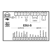
The outputs indicating “AUX OUT” on the back panel are the digital outputs of the panel. These outputs are all dry
contact relays. “COM 3” is the common for auxiliary outputs 1,2 and 3. The following functions can be assigned to
the auxiliary outputs using their respective parameters P254, P256 and P258.
If no function will be assigned to the digital output, this function should be
selcted.
If the engine has started and alarm delay time has passed this output will
be activated.
If the panel is in AUTO mode, this output will be activated.
If the Menu has been entered from the front panel, this output will be
activated.
4: B,C (Class 1 & 2) Class Alarm (Horn)
Output
In the Parameter List, the alarm classes are defined as follows;
Class A : 0
Class B : 1
Class C : 2
Class D : 3
Class E : 4
Class F : 5
Class A alarms are numerically defined as “0”.
In the case of a Class 1 or 2 alarm, this output is activated.
If the parameter P20 “Alarm Maximum Output Time” is defined as “0”,
this output will constantly be active. If parameter P20 is set at a value
which is >0, then this output will be activated for that time period then be
deactivated.
5: D,E,F (Class 3, 4 & 5) Class Alarm
(Horn) Output
In the case of a Class 3, 4 or 5 alarm, this output is activated.
If the parameter P20 “Alarm Maximum Output Time” is defined as “0”,
this output will constantly be active. If parameter P20 is set at a value
which is >0, then this output will be activated for that time period then be
deactivated.
6: B,C,D,E,F Class Alarm (Horn) Output
In the case of a Class 1, 2, 3, 4 or 5 alarm, this output is activated.
If the parameter P20 “Alarm Maximum Output Time” is defined as “0”,
this output will constantly be active. If parameter P20 is set at a value
which is >0, then this output will be activated for that time period then be
deactivated.
If there is a requirement of pre-heating before engine cranking this
function output is used. The preheat time can be set using paramter P19.
8: Generator Loaded Output
If the system is fed through the generator contactor, this output will be
 Loading...