xiii
Figures
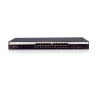
1-1 A4H124-24FX Front Panel ................................................................................................................. 1-2
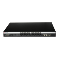
1-2 A4H254-8F8T Front Panel ................................................................................................................. 1-2
1-3 A4 Switch Back Panel ........................................................................................................................1-2
2-1 Area Guidelines for Switch Installation on Flat Surface......................................................................2-3
2-2 Attaching the Rackmount Brackets ....................................................................................................2-4
2-3 Fastening the Switch to the Rack....................................................................................................... 2-5
2-4 High-Speed Stacking Cable Connections ..........................................................................................2-6
2-5 Switch Rear View ............................................................................................................................. 2-10
2-6 STK-RPS-150PS Installation in an STK-RPS-150CH2 Shelf........................................................... 2-12
2-7 STK-RPS-150PS Installation in an STK-RPS-150CH8 Shelf........................................................... 2-13
2-8 Fastening the STK-RPS-150CH2 to the Rack.................................................................................. 2-15
2-9 Fastening the STK-RPS-150CH8 to the Rack.................................................................................. 2-16
2-10 Power Connectors on STK-RPS-150PS (rear view) ........................................................................ 2-17
2-11 STK-RPS-150PS RPS Cable and AC Power Cord Connections .....................................................2-17
2-12 DB9 Male Console Port Pinout Assignments ................................................................................... 2-18
2-13 Connecting a UTP Cable Segment to an RJ45 Port ........................................................................ 2-21
2-14 Installing an SFP Transceiver with RJ45 Connector ........................................................................ 2-23
2-15 Installing an SFP Transceiver with MT-RJ Connector...................................................................... 2-23
2-16 Installing an SFP Transceiver with an LC connector........................................................................ 2-24
2-17 Connecting a Fiber-Optic Cable Segment to Fixed MT-RJ Port....................................................... 2-26
3-1 A4 Chassis LEDs (A4H254-8F8T shown) ..........................................................................................3-2
A-1 STK-RPS-150PS Power Supply Connector Pin Locations.................................................................A-4
 Loading...