Do you have a question about the Enterasys A4H124-24 and is the answer not in the manual?
Identifies the intended audience for the guide, focusing on network administrators.
Provides guidance on how to navigate and use the document effectively for understanding features.
Lists other relevant manuals available for download, including the CLI Reference.
Explains the conventions used throughout the guide, such as notes, cautions, and warnings.
Lists old and new part numbers for power supply replacements.
Provides contact information and methods for obtaining technical support and assistance.
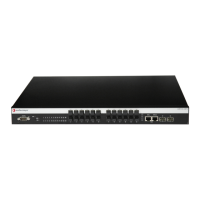
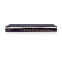
Introduces the Enterasys A4 Fast Ethernet stackable switches and their core functions.
Details the stackable switches' capabilities, management platform, and network uplink.
Explains how switches are physically interconnected in a stack configuration.
Describes the integration and benefits of optional external redundant power supplies.
Outlines the available methods for managing the switch, both in-band and out-of-band.
Details the operational behavior of the cooling fans based on ambient temperature for a specific model.
Lists the IEEE and other standards that the switch ports comply with.
Explains using the HTTP-based Web management application for configuration tasks.
Describes using CLI commands for comprehensive switch configuration management.
Essential pre-installation steps and notifications for network administrators.
Lists the specific tools needed for the installation process.
Provides step-by-step instructions for safely unpacking the switch and checking its contents.
Guides on mounting the switch on a flat surface, including the application of rubber feet.
Detailed instructions for attaching the rubber feet to the switch base for stability.
Specifies the environmental and site requirements for rack-based installations.
Covers the physical process of mounting the switch into a standard 19-inch rack.
Explains the procedures for connecting multiple switches into a stack using specific cables.
Details how switches operate and are managed when interconnected in a stack.
Describes the process by which a stack manager is elected or assigned.
Guides on installing and connecting optional redundant power supplies for increased system uptime.
Instructions for the removal of a specific redundant power supply unit.
Steps for mounting the redundant power supply shelf into a rack.
Procedures for securing the RPS chassis within a standard 19-inch rack.
Details the physical connections for the RPS cable and AC power to the power supply.
Instructions for installing the STK-RPS-500PS power supply on a non-rack surface.
Guides on connecting a PC via console port for direct switch management.
Instructions for connecting a VT Series terminal for console-based management.
Details connecting a modem to the switch for remote console access.
Explains how to connect standard network cables to the RJ45 ports.
Prepares for SFP transceiver installation, emphasizing static discharge precautions.
Step-by-step guide for inserting SFP transceivers into available ports.
Procedures for safely removing an installed SFP transceiver.
Covers the connection of fiber-optic cables to SFP ports.
Guides on performing the initial login and setup for switch management.
Defines the meaning and behavior of all LEDs on the switch chassis for status indication.
Explains the Manager (MGR) LED status for identifying the stack manager.
Describes the Redundant Power Supply (RPS) LED and its indicators.
Details the Stack UP LED status indicating connection to the stack down connector.
Details the Stack DOWN LED status indicating connection to the stack up connector.
Explains the CPU LED indications for system operational status and errors.
Describes the status of port-specific Link/Activity LEDs for RJ45 and SFP ports.
A comprehensive list of common issues, their causes, and recommended solutions.
Instructions on how to reset the switch password using the physical reset button.
Step-by-step guide for safely detaching the switch from its rack mounting.
Comprehensive specifications for A4 model switches, including ports, memory, and physical attributes.
Detailed specifications for the STK-RPS-150CH2, STK-RPS-150CH8, STK-RPS-150PS, and STK-RPS-500PS.
Physical specifications for the two-slot redundant power supply chassis.
Physical specifications for the eight-slot redundant power supply chassis.
Electrical and physical specifications for the 150W redundant power supply.
Electrical, physical, and environmental specifications for the 500W redundant power supply.
Pinout and function details for the STK-RPS-150PS power supply connector.
Pinout and function details for the STK-RPS-500PS power supply connector.
Recommended torque specifications for installing screws and bolts.
Reference to datasheets for specifications of optional pluggable SFPs.
Information on the pin configuration for the switch's console port.
Lists the product's compliance with safety, EMC, and environmental regulations.
Details the specific standards met for regulatory compliance.
| Model | A4H124-24 |
|---|---|
| Power over Ethernet (PoE) | No |
| Operating Temperature | 0°C to 50°C |
| Power Supply | 100-240V AC, 50/60 Hz |
| Type | Managed |
| Ports | 24 |
| Jumbo Frame Support | 9216 bytes |
| Weight | 4 kg |