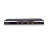
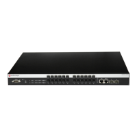
Rack Mounting the Switch
2-4 Installation
Guidelines for Rackmount Installation
The installation site must be within reach of the network cabling and meet the requirements listed
below:
• Appropriate grounded power receptacles must be located within 152 cm (5 ft) of the location.
• A temperature of between 0°C (32°F) and 50°C (122°F) must be maintained at the installation
site with fluctuations of less than 10°C (18°F) per hour.
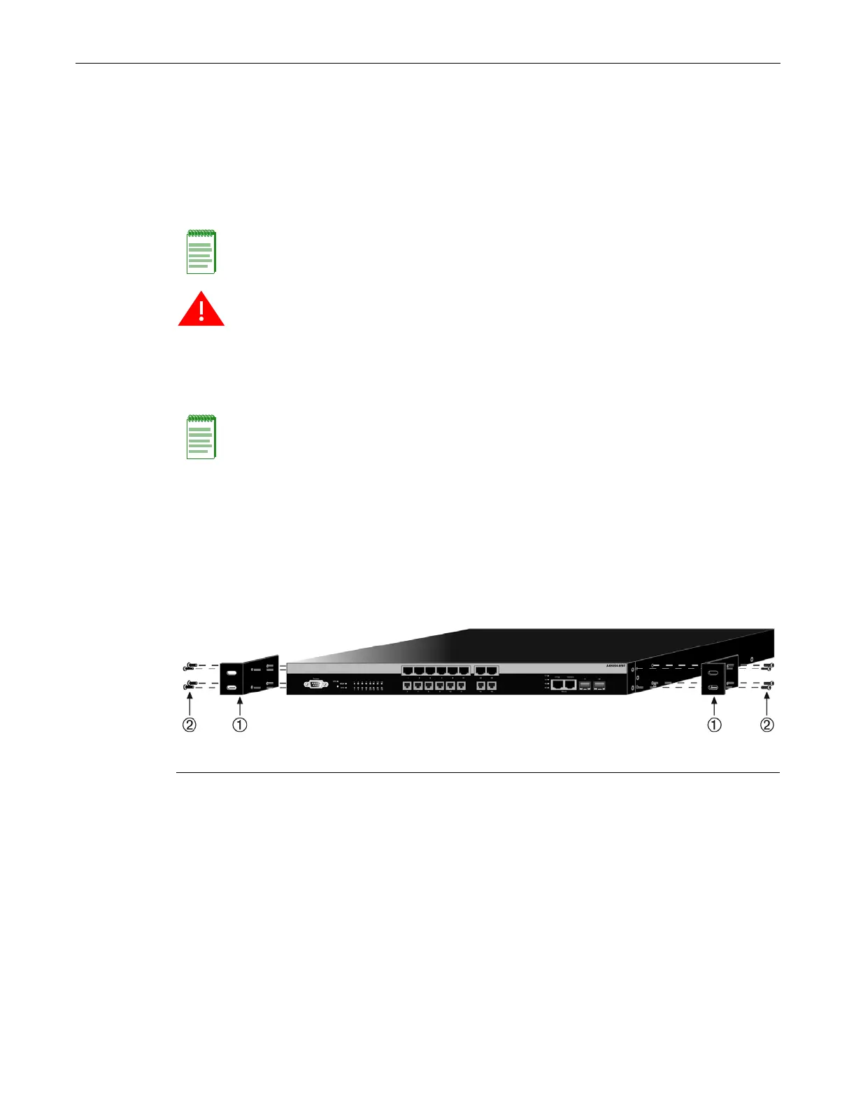
Attaching the Brackets and Installing in a Rack
Proceed as follows to install the switch into a 19-inch rack:
1. Attach the rackmount brackets to the switch, as shown in Figure 2-2, using the eight M3x6
mm flathead screws shipped with the switch.
Figure 2-2 Attaching the Rackmount Brackets
2. With the mounting brackets attached, position the switch between the vertical frame members
of the 19-inch rack as shown in Figure 2-3. Then fasten the switch securely to the frame using
four customer-supplied mounting screws.
Note: To ensure proper ventilation and prevent overheating, leave a minimum clearance space of
5.1 cm (2.0 in.) at the left and right of the switch.
Warning: Before rack-mounting the switch, ensure that the rack can support it without
compromising stability. Otherwise, personal injury and/or equipment damage may result.
Advertencia: Antes de montar el equipo en el rack, asegurarse que el rack puede soportar su peso
sin comprometer su propia estabilidad, de otra forma, daño personal o del equipo puede ocurrir.
Warnhinweis: Überzeugen Sie sich vor dem Einbau des Gerätes in das Rack von dessen
Stabilität, ansonsten könnten Personenschäden oder Schäden am Gerät die Folge sein.
Note: Do not install the rubber feet if you are rack mounting the switch.
1 Rackmount brackets 2 M3x6 mm flathead screws
 Loading...