Installing and Connecting a Redundant Power System
Enterasys A4 Fast Ethernet Switch Hardware Installation Guide 2-17
.
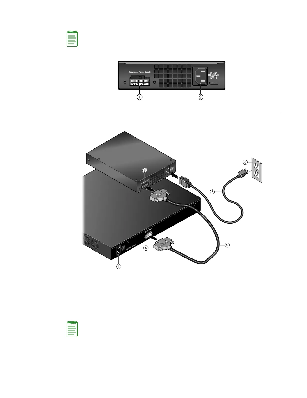
Figure 2-10 Power Connectors on STK-RPS-150PS (rear view)
Figure 2-11 STK-RPS-150PS RPS Cable and AC Power Cord Connections
4. If the switch itself is not plugged into power, the front panel RPS LED indicator will show that
a redundant power supply is now in operation.
.
This completes the installation.
Note: No change in switch configuration is necessary for this installation.
1 Redundant power supply connector 2 AC power connector
1 A4 switch 4 A4 switch redundant power supply connector
2 RPS cable (1 meter long) 5 AC power cord (type varies depending on country)
3 STK-RPS-150PS redundant power supply
connector
6 AC power outlet with ground connection
(type varies depending on country)
Note: No change in switch device configuration is necessary for this installation.

 Loading...