Rack Mounting the Switch
2-4 Installation
Ifyouareinstallingseveralswitchesinastack,proceed to“ConnectingHigh‐SpeedStacking
Cables”onpage 2‐6. Iftheswitchisbeinginstalledasastandaloneswitch,proceedto
“ConnectingACPower”onpage 2‐10forpowerconnectioninstructions.
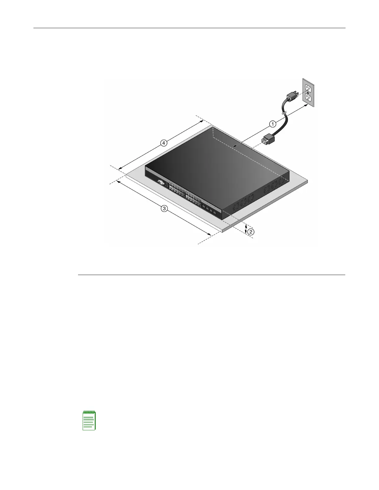
Figure 2-2 Area Guidelines for Switch Installation on Flat Surface
Rack Mounting the Switch
Toinstalltheswitchina19‐inchrack,youneed:
•Tworackmountbracketsandmountingscrews(rackmountkit)shippedwiththeswitch.
•Fourcustomer‐suppliedscrewstoattachtheswitchtoastandard19‐inchrack.
Guidelines for Rackmount Installation
Theinstallationsitemustbewithinreachofthenetworkcablingandmeettherequirementslisted
below:
• Appropriategroundedpowerreceptaclesmustbelocatedwithin152cm(5ft)ofthelocation.
•Atemperatureofbetween0°C(32°F)and50°C(122°F)mustbemaintainedattheinstallation
sitewithfluctuationsofless
than10°C(18°F)perhour.
1 Approximately 152 cm (5 ft) from power source 3 44.5 cm (19.4 in.) for proper ventilation
2 4.45 cm (1.75 in.) per switch. (Vertical clearance
depends on number of switches stacked.)
4 41.9 cm (16.5 in.) for proper ventilation
Note: To ensure proper ventilation and prevent overheating, leave a minimum clearance space of
5.1 cm (2.0 in.) at the left and right of the switch.
 Loading...