xii
Using the OFFLINE/RESET Button .............................................................................................................. 3-17
Recommended Shutdown Procedure Using OFFLINE/RESET Button ................................................. 3-17
Last Resort Shutdown Procedure Using OFFLINE/RESET Button ....................................................... 3-17
Appendix A: Specifications
SSA Specifications .........................................................................................................................................A-1
Pluggable Transceiver Specifications .............................................................................................................A-2
COM Port Pinout Assignments .......................................................................................................................A-2
Regulatory Compliance ..................................................................................................................................A-3
Appendix B: Resetting Mode Switches
Required Tools ...............................................................................................................................................B-2
About the Mode Switches ...............................................................................................................................B-2
Setting the Mode Switches .............................................................................................................................B-4
Appendix C: About PoE (Power over Ethernet)
Overview .........................................................................................................................................................C-1
Proprietary PD Detection ................................................................................................................................C-1
PoE Port Status LEDs ....................................................................................................................................C-2
Allocation of PoE Power to Devices ...............................................................................................................C-2
Power Distribution Upon Power Supply Removal or Addition ........................................................................C-2
Management of PoE Power to PDs ................................................................................................................C-3
Figures
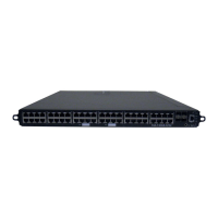
1-1 SSA-T4068-0252 Front Panel ............................................................................................................ 1-1
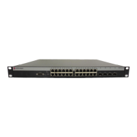
1-2 SSA-T1068-0652 Front Panel ............................................................................................................ 1-2
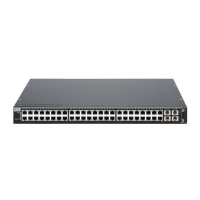
1-3 SSA-G1018-0652 Front Panel............................................................................................................ 1-2
2-1 Attaching the Rails to a Four-post Rack ............................................................................................. 2-5
2-2 Securing the SSA in a Four-post Rack............................................................................................... 2-6
2-3 Removing the Rail Extensions............................................................................................................ 2-7
2-4 Attaching the Mounting Brackets to the Rails (Left Rail Example) ..................................................... 2-8
2-5 Positioning and Attaching the Rails to the 7-inch Posts ..................................................................... 2-8
2-6 Installation Positions in a Two-post Rack (3-inch Posts).................................................................. 2-10
2-7 Screw to Remove if You Plan to Secure the Left Rear of the SSA .................................................. 2-11
2-8 Securing the Rear of the SSA (Four-post Rack Example) ............................................................... 2-11
2-9 SSA Ground Receptacle .................................................................................................................. 2-13
2-10 Installing a Power Supply ................................................................................................................. 2-13
2-11 Connecting Power to the SSA .......................................................................................................... 2-14
3-1 RJ45 Port LEDs.................................................................................................................................. 3-1
3-2 SFP and SFP+ Port LEDS.................................................................................................................. 3-2
3-3 SSA System LEDs.............................................................................................................................. 3-3
3-4 SSA Fan Locations............................................................................................................................. 3-8
3-5 Removing the Side Panel of the SSA................................................................................................. 3-9
3-6 Underside of the SSA Side Panel..................................................................................................... 3-10
3-7 Disconnecting an F1–F7 Fan (Fan F3 Example).............................................................................. 3-10
3-8 Connecting an F1–F7 Fan (Fan F3 Example) .................................................................................. 3-11
3-9 Removing a Fan’s Cable Clip ........................................................................................................... 3-12
3-10 Connecting an F8–F10 Fan (Fan F8 Example) ................................................................................ 3-
13
3-11 Removing the Rear Panel ................................................................................................................ 3-14
3-12 Underside of the SSA Rear Panel .................................................................................................... 3-15
3-13 Disconnecting an F11–F13 Fan (Fan F11 Example)........................................................................ 3-15
3-14 Connecting an F11–F13 Fan (Fan F11 Example) ............................................................................ 3-16
3-15 OFFLINE/RESET Button .................................................................................................................. 3-17
B-1 Mode Switch Location ........................................................................................................................B-3

 Loading...


