9
ENTRON Controls, LLC. 700230D
9
3.1 Install and Setup
For wall-mount dimensions, refer to the ENTRON Cabinet Guide (doc 780054) on our website.
1. Ensure that all power is removed before connecng the control.
2. Connect the chassis ground to an external earth ground.
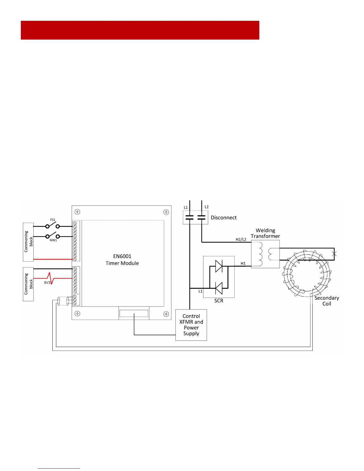
3. Connect L1, L2, and H1 as shown in the “CUSTOMER CONNECTIONS” secon of the wiring diagram. An H1 connecon will be
required for each transformer in a mulple-control layout.
4. Using the wiring diagram, verify the T1 jumper connecon properly corresponds with the line voltage.
5. Ensure that all electrical and mechanical connecons are ghtly secured.
6. Connect cooling water as required.
7. Connect any necessary foot switches, valves, E-Stop switches, pressure switches, etc. as demonstrated below.
 Loading...