3 Begin to use
7 8
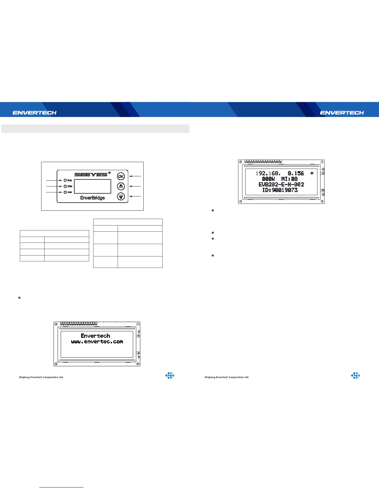
3.1 LCD of EVB202
The LCD displays the device’s operation satusand realtime system data. It helps users
to check the system status timely and conveniently.
When EVB202 displays the Start-up interface, the first line shows the company
name “Envertech” and the second line shows the company website
“www.envertec.com”.
Start-up time: 30s,as shown below:
3.1.2 Start-up Interface
After EVB202 is started, it will enter normal working status. At this moment the
LCD will display the monitoring information.
First line: IP address;
Second line: Power & quantity of microinverters
Third line: EVB version;
Fourth line: EVB ID number (as shown below):
IP address will be shown on the first line of the screen, for example:
192.168.9.150. If the first line shows 192.168.0.255, it means there is no
connection with the server. A‘*’stands for successful connection with the
server, and no‘*’stands for no connection.
Real-time power, is displayed at the beginning of the second line.
The quantity of microinverter is displayed at the end of the second line, which
means how many MIs have successfully transmitted data. On the third line it
shows the software version: EVB202-E-N-002.
On the fourth line it shows the EnverBridge ID: each EnverBridge owns only
one ID. For example, this EnverBridge’s ID is 90019073.
In the newly installed monitoring system, you firstly need to set the microinverter ID
on the EVB202. It is recommended to set the microinverter ID before installing it into
the power station. For details, please see the following sector 3.1.3..
3.1.3 Selection Interface
Press “OK”button (Backlight lights up automatically) to enter [Menu Interface]
which is shown as shown below.
* Monitor Interface
* Total Energy
* MI Status
* Set MI SafetyParam
* Set MI ID
* Set EVB ID
* Reset MI
* Restart System
There are a total of eight operations. Press “Up” and “Down” to move the
cursor to view all functions. Press “OK” to enter the function.
3.1.1 Description of LCD