5. Confirm if the microinverter side is connected to the grid by measuring the
voltage from AC line to line and line to neutral.
6. Visually check if AC branch circuit connection is correctly done. Reinstall if
necessary.-Check also for damage, such as rodent damage.
7. Make sure that all circuit breakers are off.
8. Disconnect and re-connect the PV modules’ DC connectors with
microinverters. The LED status of each microinverter will blink green to indicate
normal start-up operation soon after DC power is applied (less than one minute).
9. Attach an ammeter clamp to one conducting wire of the DC cables from the
PV module to measure the microinverter’s current. This will be under 1 Amp if
AC is disconnected.
10. Check the DC connection between the microinverter and the PV module. The
connection may need to be tightened or reseated. If the connection is worn out
or damaged, it needs replacement.
11. Verify with your utility company that grid frequency is within the regulated
range.
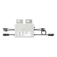
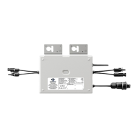
7.3 Disconnect Microinverters from PV Modules
If your problems are still unsolved with the steps above, please contact
Envertech tech support through www.envertec.com. If Envertech approves the
replacement, please take off the microinverter according to the following
instructions. In order to ensure the disconnection between the microinverter
and the PV Module will not be done while the microinverter is at working status,
please strictly follow the steps below.
1. Turn off AC branch circuit breaker.
2. Disconnect the microinverters in the following procedure.
Pull the AC connectors of both sides of the microinverters in the opposite
direction with appropriate force.
3. Cover the PV module with an opaque, and then disconnect the PV module DC
connectors from the microinverter.
4. Loosen the grounding screw and remove the grounding wire.
5. Take off the microinverter from the PV frame.
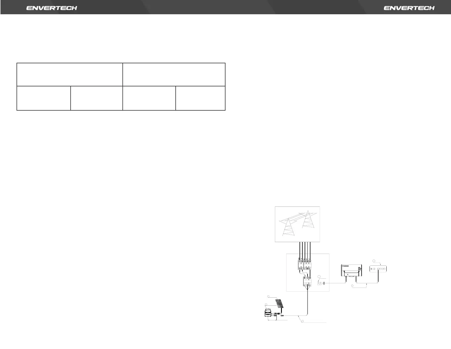
8. System Diagram
1. Single phase