the plug to connect to the socket
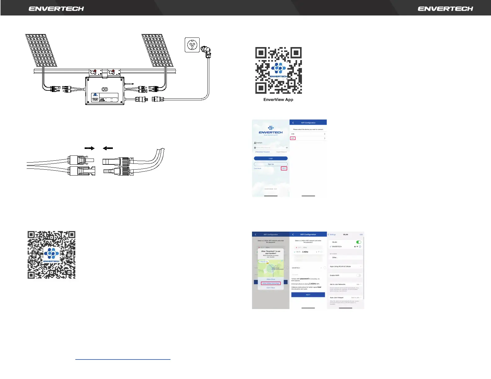
Step 7. Connect PV modules to microinverters
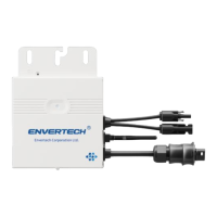
Mount the PV modules on top of the microinverters; Connect each PV
module with the DC input cables of the microinverter.
Step 8. Switch on the PV system
Ensure all connection is completed and then turn on the air switch.
For the monitoring system (EnverBridge) installation please scan this
QR
code
.
EnverBridge Installation
Step 9. WIFI Configuration
Option
1. Use Enverview app to configure WiFi
Note: Please place the EVT800 as close as possible to the router.
The EVT800 has built-in WIFI modular which is able to connect the router directly.
Web Portal address: https://www.envertecportal.com/
To access our application, you can scan the QR code provided below or search
for 'Enverview' on Google Play Store or Apple Store for download.
a. Open Enverview app and click WiFi. Select “EVT” to connect.
b. Select a 2.4GHz WiFi network, and return to the app. Then enter the password
of 2.4GHz WiFi network. Please allow Enverview app to use your location. Or
you will fail to configure WiFi.
Note:
1. Please carefully check the WiFi password, such as extra spaces.
2. Ensure that the WiFi name and password do not contain , ; = or other special
characters.
12
User Identification Number
-40
℃
to +65
℃
Temperature(
℃
):
Operating Range (Vdc):
16V~60V
Normal Voltage?(Vac):
220/230V
MPPT Voltage Range (Vdc):
22V~50V
Current (Max. Continuous) (A):
3.63A
Max. DC Input (Vdc):
60V
Frequency?(Hz):
50Hz/60Hz
Max. Input Continuous Current?(A):
14Ax2
Power Factor Range:
+/-0.90
Max. Input Short-Circuit Current (A):
25A Maximum Units Per Branch: 6
Power (Max. Continuous) (W):
800W
Overvoltage Category: OVC III (AC Main), OVC II ( PV)
Ingress Protection (IP):
IP67 Protective Class: Class I
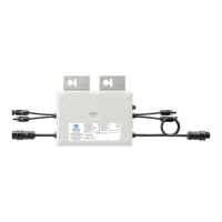
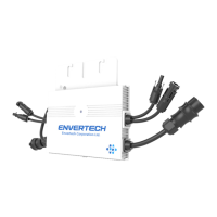
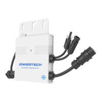
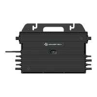
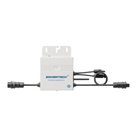
Model: EVT800
www.envertec.com
Envertech(Shanghai)Corporation LTD.
PV Microinverter