Step 6:
Feed the stretched venting into the exterior hole and
down the chimney. This kit can be used from 3’-7’ (see
Table 1), trim any excess vent as needed. Mount the
wall terminal to the chimney with screws. Seal as per lo-
cal codes and regulations.
Step 7:
Ensure that the vent length is correct, and the venting is
not crimped or overstretched.
Step 8:
Attach the venting to the top of the replace using 3
screws per vent. Making sure the intake is on the intake
collar. The intake collar is on the left side of the replace
for the Q1 and is indicated on the ue collar of the E
series units by the “IN”.
1 OF 1
SHEET
Part Description
FINISH
SCALE- NOT TO SCALE
HEAT TREATMENT
Sherwood Industries Ltd.
MATERIAL
UNLESS OTHERWISE SPECIFIED
+/- .002
Hole Pos.
+/- .5
Angles
+/- .005
General
DIMENSIONS APPLY AFTER PLATING OR
HEAT TREATMENT
THREADS EXTERNAL CL 2A INTERNAL CL 2B
TOLERANCE
ALL DIMENSIONS IN INCHES
+/- .001
Hole Size
APPROVAL
CHECKED BY
DRAWN BY
THIS DRAWING IS THE PROPERTY OF SHERWOOD INDUSTRIES LTD. AND MAY NOT BE COPIED, REPRODUCED, OR OTHERWISE DISCLOSED WITHOUT THE PRIOR APPROVAL OF SHERWOOD INDUSTRIES LTD.
10/4/2018
REV
Roughly 6-3/4”
Roughly
5-3/4”
Roughly 5”
3” Dia.
4” Dia.
Exterior View
1 OF 1
SHEET
Part Description
FINISH
SCALE- NOT TO SCALE
HEAT TREATMENT
Sherwood Industries Ltd.
MATERIAL
UNLESS OTHERWISE SPECIFIED
+/- .002
Hole Pos.
+/- .5
Angles
+/- .005
General
DIMENSIONS APPLY AFTER PLATING OR
HEAT TREATMENT
THREADS EXTERNAL CL 2A INTERNAL CL 2B
TOLERANCE
ALL DIMENSIONS IN INCHES
+/- .001
Hole Size
APPROVAL
CHECKED BY
DRAWN BY
THIS DRAWING IS THE PROPERTY OF SHERWOOD INDUSTRIES LTD. AND MAY NOT BE COPIED, REPRODUCED, OR OTHERWISE DISCLOSED WITHOUT THE PRIOR APPROVAL OF SHERWOOD INDUSTRIES LTD.
10/4/2018
REV
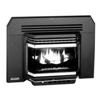
Exhaust
Intake
Step 4:
Prebend the intake and exhaust
venting, do NOT exceed 90
degrees. After the elbow, stretch
the venting to the desired verti-
cal height.
Step 5:
Attach the venting to the wall
terminal using the supplied hose
clamps. Note the exhaust inlet
is the inlet with the reducer as
seen in the Figure 2.
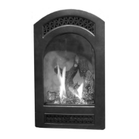
Figure 1: Cut-out size
Figure 2: Top View
Initial Installation
QUALIFIED INSTALLERS ONLY
Step 9 [E30 & E33 installations only]:
Set the adjustable plate located in the rebox bafe to the most open position using a Torx T20
screwdriver. Refer to the Owner’s Manual for further information.
Step 3:
Proceed to core or drill a hole at the predetermined height. Figure 1 provides dimensions for the re-
quired cut-out.
Figure 1: Cut-outs
NOTE: Holes are
orientated at a 40
degree angle