7
GB
The Infratec Classic control units with-
out pre-installed cables (item no. 94.4388)
shall be connected only with the cable resist-
ant to at least 90°C according to the given
below connection diagram.
• Only IR radiators as per DIN 60335 or
IR heating foils with integrated overheat-
ing protection (140°C) may be connected.
• Follow the safety and installation infor-
mation provided by the IR radiant heater
manufacturer.
Installation of the lighting
• The connection cable is to be fed through
the hole drilled beforehand, and is to be con-
nected to the cabin lighting.
• The cabin lighting must always be mounted
as far as possible from the positional spot of
the infrared emitter, and may not be placed
within the direct heat radiation angle.
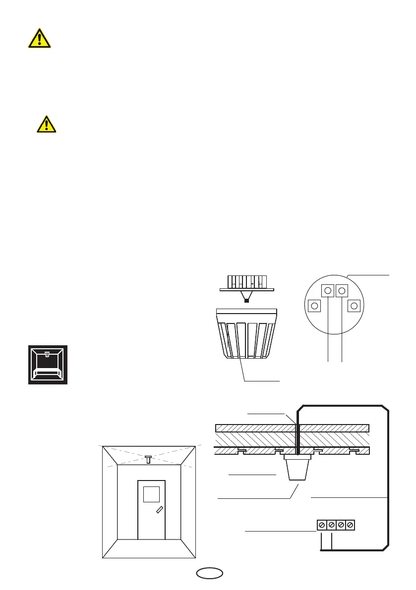
1. The temperature sensor shall be mounted in
the centre of the cabin ceiling.
2. Drill a hole to lead the cable through the ceil-
Housing
Sensor circuit
board
Sensor
Ceiling panel hole
Cabin ceiling
Centre sensor housing on
middle section
Sensor cable
Terminals in control unit
ing, preferably through the middle of one of
the wooden boards.
3. Guide the sensor cable through the drilled
hole.
4. Connect the sensor cable to the sensor board
terminals as shown below.
5. Attach the sensor board to the ceiling with
two included screws and t the sensor hous-
ing (cap) to the board. Make sure it sits tightly.
6. Connect the sensor cable to the control unit
terminals as shown on the connection dia-
gram. See illustration below for details.
Installation of the tempera-
ture sensor