20
EN
Installation and operation from the
left
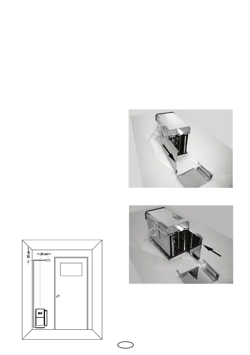
To install and operate the unit from the left,
the front and rear panels must be exchanged.
To do this, lay the unit on the side opposite the
operating side.
Loosen and remove the two screws holding the
base to the unit from the underside of the base.
Then pull the front panel down and out of the
side housing components (as was done with
the rear panel) (Fig. 6) and push it back into the
housing frame on the opposite side (Fig. 7).
Turn the base 180° and refasten it to the housing.
The eye plates on the side must hold the front
panel rmly in place.
Sensor installation
The built-in control unit is equipped with
a thermostat and an a temperature limiter.
The capillary tube sensors are delivered with
the heater unit (packed in the lower section
of the heater). The sensor must be removed
carefully from the heater and xed in position
in the mounting holes on the sensor mounting
bracket. The capillary tubes must not be bent
or damaged. The smallest bending radius
should not be less than 4-5 cm during and
after installation.
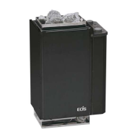
The sensor mounting bracket is mounted
(using the provided wood screws) to the cabin
wall as shown in Fig. 5, centered above the
heater exhaust outlet facing the cabin door
and positioned 25 cm below the cabin ceiling,
The bracket must be placed in this position, as
otherwise the desired temperatures cannot be
achieved. The excess length of capillary tube
should be rolled up behind the heater and
must not be pushed back into the connection
box under any circumstances.
If the installed capillary tubes do not have an
insulating mantle, they must be protected
against contact. This can be accomplished by
running the tubes through the grooves in the
wall paneling and covering them with appro-
priate wood strips.
Attention! The capillary tubes must not be
damaged!
Fig. 5
Fig. 6
Fig. 7