19
EN
The delivery package includes the following
components:
1 sauna heater
1 accessory bag, including: 4 tension-plate
screws
1 set of sauna stones
Power intake: 3 kW
Cabin size: 4,0 m³
Minimum Diameter
for fresh air intake: 20 x 4 cm
Hight: 60 cm
Width: 30 cm
Depth: 20 cm
Main power supply: 230 V N AC
Fuse: 16 A
When used for commercial purposes, the sauna
heater may only be used in combination with the
rocker switch Type I Art. No. 94.4421.
Technical data
Installation
Minimum clearances
The sauna cabin must have a minimum inside
height of 1.90 m.
During installation of the sauna heatingunit, it
is important to ensure that the vertical distance
between the upper surface of the sauna heating
unit and the sauna cabin ceiling is not less than
90 cm. The required horizontal (lateral) distance
between the sauna heating unit and the cabin
wall is shown in the dimensional diagram for the
each specic sauna heating unit. The distance
between the lower surface of the sauna heating
unit and the oor is also indicated in the dimen-
sional diagram.
Remove the sauna heating unit from the pa-
ckaging and pull o the protective foil on the
stainless steel and exterior housing components.
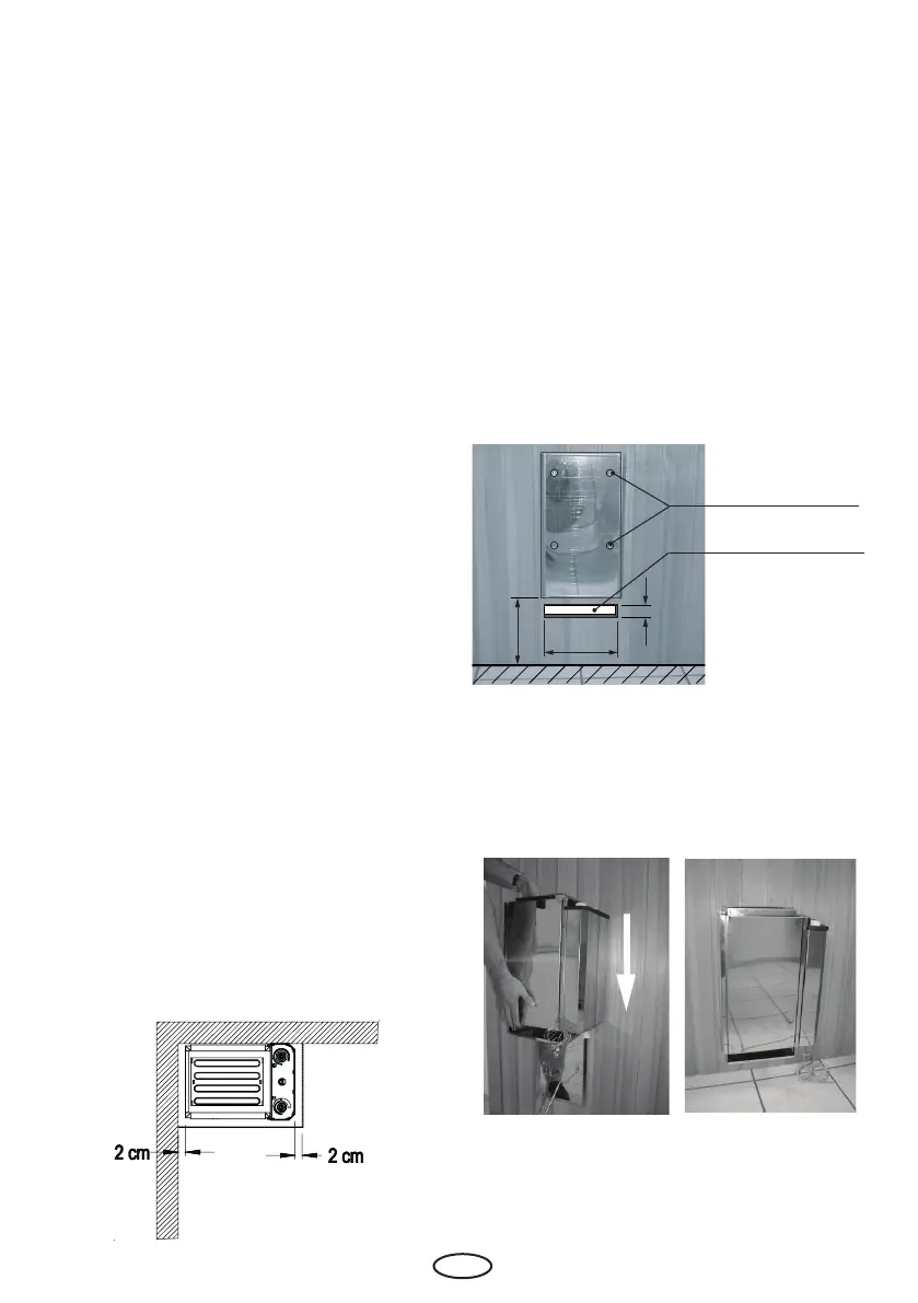
To install the unit, the rear wall is rst removed
from the unit by pulling it downward while the
unit is tilted or lying on its side.
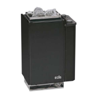
Mount the rear wall panel to the cabin wall
using the enclosed 4 tension plate screws in
accordance with the dimensions shown in Fig. 2.
Caution! The cams of the mounting holes
must not be set in a groove, as this will create
a space between the rear wall of the heater
and the cabin wall.
Fig. 1
Holes always positi-
oned in the center
of a profile panel
Fig. 2
Fresh-air inlet
Next, set the heater unit onto the rear wall from
above. Ensure that the vertical angular segments
of the side walls are ush with the cabin wall
(Fig. 3 and 4).
Fig. 3
Fig. 4
Drill a hole measuring approx. 12 mm in diame-
ter near the fresh-air inlet and push the power
cable through this hole to the cabin exterior.
22 cm
20 cm
4 cm