9
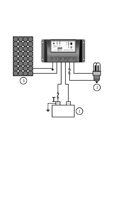
Step 4: Confirm Wiring
Double-check the wiring in step1 through 3. Confirm correct polarity at each
connection. Verify that all six terminals are tightened.
Figure 3-5 System wiring review
Step 5: Confirm power on
When battery power is applied and the controller starts up, the battery LED
indicator will be green.
If the controller doesn't start up, or the battery status LED error exists, please
refer to section 5 for troubleshooting.