L120 Revision A
Confidential
Maintenance Lubrication Points and Instructions 55
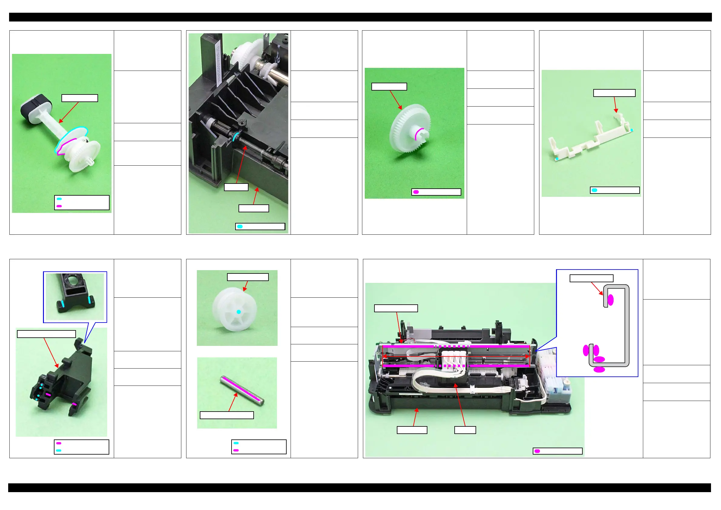
Figure 4-5. Lubrication of the LD Roller Assy Figure 4-6. Lubrication of the EJ Roller
<Part supply as ASP>
Yes
<Lubrication status when
supplied as ASP>
Not lubricated
<Lubrication Point>
1. Cam of the LD Roller
Assy (contact point with
the Hopper)
2. Cam of the LD Roller
Assy (contact point with
the Paper Back Lever)
<Type>
G-71
<Application Amount>
Circumference of each
cam (0.05 g each)
<Remarks>
Apply with injector.
Lubricate before
attaching the part.
LD Roller Assy
2. Application Point
1. Application Point
<Part supply as ASP>
Yes
<Lubrication status when
supplied as ASP>
Not lubricated
<Lubrication Point>
Contact point (x1 on the
shaft) on the EJ Roller with
the Frame Base
<Type>
G-71
<Application Amount>
0.06 g
<Remarks>
Apply with injector.
Lubricate before
attaching the part.
EJ Roller
Application Point
Frame Base
Figure 4-7. Lubrication of the EJ Roller Gear Figure 4-8. Lubrication of the Paper Back Lever
<Part supply as ASP>
Yes
<Lubrication status when
supplied as ASP>
Not lubricated
<Lubrication Point>
Shaft on the EJ Roller Gear
<Type>
G-71
<Application Amount>
1 mm x 1 circle
<Remarks>
Using injector, apply
grease along the tier on
the shaft.
Lubricate before
attaching the part.
EJ Roller Gear
Application Point
<Part supply as ASP>
Yes
<Lubrication status when
supplied as ASP>
Not lubricated
<Lubrication Point>
Contact points (x2) on the
Paper Back Lever with the
Frame Base
<Type>
G-71
<Application Amount>
0.06 g x 2 points
<Remarks>
Apply with injector.
Lubricate before
attaching the part.
Paper Back Lever
Application Point
Figure 4-9. Lubrication of the CR Driven Pulley Assy Figure 4-10. Lubrication of the CR Driven Pulley/
CR Driven Pulley Shaft
<Part supply as ASP>
None
<Lubrication status when
supplied as ASP>
---
<Lubrication Point>
1.
On the bearings (x2) of the
CR Driven Pulley on the
CR Driven Pulley Holder
2. Contact points (x6) on
the groove of the CR
Driven Pulley Holder
with the Main Frame
<Type>
G-71
<Application Amount>
Appropriate amount
<Remarks>
Apply with injector.
Check the lubrication
condition and apply
grease if necessary.
2. Application Point
1. Application Point
<Part supply as ASP>
None
<Lubrication status when
supplied as ASP>
---
<Lubrication Point>
1.
Shaft hole of the Driven
Pulley.
2. CR Driven Pulley Shaft
<Type>
G-71
<Application Amount>
Appropriate amount
<Remarks>
Apply with injector.
2. Application Point
1. Application Point
Figure 4-11. Lubrication of the Main Frame Assy
<Part supply as ASP>
None
<Lubrication status when
supplied as ASP>
---
<Lubrication Point>
1. Contact point (x1) on
the upper side of the
Main Frame Assy with
the CR Unit
2. Contact points (x4) on
the lower side of the
Main Frame Assy with
the CR Unit
<Type>
G-71
<Application Amount>
Appropriate amount
<Remarks>
Apply with injector.
CR Unit
Application Point
Main Frame Assy
Frame Base

 Loading...