L120 Revision A
Confidential
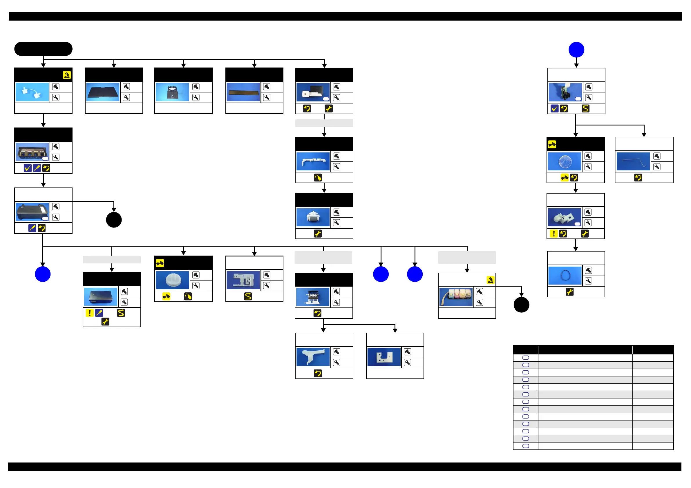
Disassembly/Reassembly Disassembly Flowchart 29
(p 31)
2
2.2.1 Disassembly Flowchart
Flowchart 2-1. Disassembly Flowchart (1)
Screw type/torque list
Symbol Screw Type Torque
C.B.P-TITE SCREW 2.6x5 F/ZN-3C 2.55 0.05 kgf·cm
C.B.P-TITE SCREW 2x8 F/ZN-3C 2.55 0.05 kgf·cm
C.B.P-TITE SCREW 2x8 F/ZN-3C 2
0.5 kgf·cm
C.B.P-TITE SCREW 3x10 F/ZB-3C 6 1 kgf·cm
C.B.P-TITE SCREW 3x10 F/ZN-3C 6
1 kgf·cm
C.B.P-TITE SCREW 3x10 F/ZN-3C 7 1 kgf·cm
C.B.S-TITE (P2) SCREW 3x6 F/ZN-3C 7
1 kgf·cm
C.B.S-TITE (P2) SCREW 3x6 F/ZN-3C 8 1 kgf·cm
C.B.S-TITE SCREW 3x6 F/ZN-3C 6
1 kgf·cm
C.B.S-TITE SCREW 3x6 F/ZN-3C 7.3 0.1 kgf·cm
C.B.S-TITE SCREW 3x8 F/ZN-3C 7.3
0.1 kgf·cm
C.P SCREW 2.6x3 F/ZN-3C 4 0.5 kgf·cm
C.P.S-TITE (S-P1) SCREW 3x6 F/ZN-3C 7.5
0.5 kgf·cm
S1
S2
S3
S4
S5
S6
S7
S8
S9
S10
S11
S12
S13
A
Paper Support
Assy
---
1
---
Waste Ink Pad
Assy
1
2
(p 34) (p 42)
S5
Paper Back
Lever
---
2
(p 52)
Retard Roller
Assy
---
2
(p 42)
PS Unit
---
2
(p 34) (p 40)
(p 42)
EJ Roller Gear
---
---
(p 34) (p 52)
Extension Spring (x2)
FFC Holder
---
1
(p 40)
C
(p 31)
Printer Cover
---
2
---
B
(p 29)
Cable (CN501)
START
Cap Tank
---
2
---
Housing Upper
Assy
4
3
(p 34)
S5
Ink Supply Tank
Upper Housing
2
2
(p 37)
S4
Paper Support
Joint
---
3
---
Cap Lever
---
---
(p 35)
Extension Spring (
2)
Pump Tube
Porous Pad for
Cap Assy
---
---
---
Cap Assy
---
3
(p 35)
PF Scale
---
---
(p 36)
PF Timing Belt
---
---
(p 42)
PF Driven Pulley
Assy
1
1
(p 35) (p 42)
S7
PF Grounding
Spring
---
1
(p 34)
(p 31)
1
B
(p 29)
(p 30)
PF Encoder
Sensor*
1
---
(p 36) (p 40)
S2
Note "*": Proceed to the next step
with the part detached
temporarily because the
part cannot be removed
fully there.
Ink Supply Tank Tube
Assy
Ink Supply Tank
Assy
---
---
---

 Loading...