EasyManua.ls Logo

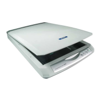
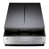
Epson Perfection 1670 Photo User Manual

Epson Perfection 1670 Photo
46 pages
To Next Page IconTo Next Page
Page #1 background imageLoading...
Page #1 background image
EPSON Perfection 1670 Photo
Perfection 1270
Color Image Scanner
®
Service Manual
SESC03-002

Other manuals for Epson Perfection 1670 Photo

Questions and Answers:

Epson Perfection 1670 Photo Specifications

Scanning Specifications IconScanning Specifications
maximum scan area8.5" x 11.7" (216mm x 297mm)
optical resolution1600 dpi
hardware resolution1600 x 3200 dpi maximum
maximum resolution13, 600 x 18, 720 dpi
color depth48-bit internal/48-bit external
grayscale depth16-bit internal/16-bit external
Interface and Speed IconInterface and Speed
interfaceUSB 1.1/2.0
scanning speed monochrome7.68 msec/line (approx.)
scanning speed full color7.68 msec/line (approx.)

Summary

PRECAUTIONS

DANGER

Signals a precaution which, if ignored, could result in serious or fatal personal injury. Great caution should be exercised in performing procedures preceded by DANGER Headings.

WARNING

Signals a precaution which, if ignored, could result in damage to equipment.

About This Manual

Manual Configuration

Describes the manual's structure, consisting of chapters and appendix.

Symbols Used in this Manual

Explains various symbols used to provide additional information or warn of danger during procedures.

Chapter 1 TROUBLESHOOTING

1.1 Overview

Explains the troubleshooting procedures for the product.

1.2 Self-diagnostic Function

Describes how the scanner self-checks its operating status and displays error definitions with LEDs.

1.3 Troubleshooting

Explains troubleshooting based on superficial phenomena and provides reference tables for phenomena and solutions.

Chapter 2 DISASSEMBLY/ASSEMBLY

2.1 Overview

Explains procedures for disassembling major units and parts.

2.1.1 Precautions

Lists safety precautions to be read before starting disassembly or reassembly.

2.1.2 Used Tools

Lists specified tools required for product disassembly and reassembly.

2.1.3 Screws Used in Disassembly and Reassembly

Details the abbreviations and list of screws used in disassembly and reassembly procedures.

2.2.1 Removal of TPU Unit

Step-by-step instructions for removing the TPU Unit.

2.2.2 Removal of Upper Housing

Step-by-step instructions for removing the Upper Housing.

2.2.3 Removal of I/F Board

Step-by-step instructions for removing the I/F Board.

2.2.4 Removal of Carriage Unit

Step-by-step instructions for removing the Carriage Unit.

2.2.5 Removal of CR Motor

Step-by-step instructions for removing the CR Motor.

2.2.6 Removal of Panel Board

Step-by-step instructions for removing the Panel Board.

2.2.7 Removal of Pulley Set and Pressure Spring

Step-by-step instructions for removing the Pulley Set and Pressure Spring.

2.2.8 Removal of TPU Inverter Board

Step-by-step instructions for removing the TPU Inverter Board.

2.2.9 Removal of Hinge Holders

Step-by-step instructions for removing the Hinge Holders.

Chapter 4 MAINTENANCE

4.1 Overview

Explains maintenance work to keep the product in best condition and prevent problems.

4.1.1 Cleaning

Provides guidelines for cleaning the exterior, document glass, and scanner interior.

4.1.2 Lubrication

Details lubrication requirements, specified grease, and lubrication points for the carriage unit.

Chapter 5 APPENDIX

5.1 Overview

Provides supplementary information useful for servicing the product.

5.1.1 Scanner Connection Diagram

Shows the connection diagram of the scanner's internal components.

5.1.2 Connector Connection Table

Lists connectors provided for each board, their descriptions, and reference tables.

5.1.3 Connector Wiring Table

Details the wiring of connectors on various boards.

5.2 Circuit Diagrams

Indicates that control electrical circuit diagrams are shown on the following pages.

5.3 Parts List, Exploded Diagram

States that an exploded diagram is not provided in this manual and refers to another document.

Related product manuals