as follows:
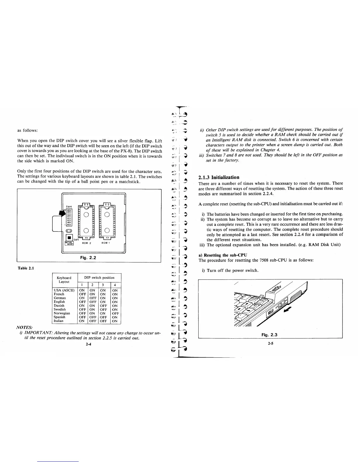
When you open the
DIP
switch cover you will see a silver flexible flap. Lift
this out
of
the way
and
the
DIP
switch will be seen
on
the left (if the
DIP
switch
cover
is
towards you
as
you are looking
at
the base
of
the PX-8). The
DIP
switch
can then be set. The indivisual switch
is
in the
ON
position when it
is
towards
the side which
is
marked ON.
Only the first four positions
of
the
DIP
switch are used for the character sets.
The settings for various keyboard layouts are shown in table 2.1. The switches
can be changed with the tip
of
a ball point pen
or
a matchstick.
0 0
0
0
ROM
2
ROM 1
Fig.
2.2
Table 2.1
Keyboard
DIP
switch position
Layout
1
2
3
4
USA
(ASCII)
ON
ON
ON
ON
French
OFF
ON
ON
ON
German
ON
OFF
ON
ON
English
OFF
OFF
ON
ON
Danish
ON
ON
OFF
ON
Swedish
OFF
ON
OFF
ON
Norwegian
OFF
ON
ON
OFF
Spanish
OFF
OFF
OFF
ON
Italian
ON
OFF
OFF
ON
NOTES:
i)
IMPORT
ANT.· Altering the settings will
not
cause any change to occur un-
til
the reset procedure outlined in section 2.2.5
is
carried out.
2-4
'1'
)
ii)
Other
DIP
switch settings are used
for
different purposes. The position
of
switch 5 is used to decide whether a
RAM
check should be carried
out
if
an Intelligent
RAM
disk
is
connected. Switch 6
is
concerned with certain
characters output to the printer when a screen
dump
is carried out. Both
of
these will be explained in Chapter
4.
iii)
Switches 7 and 8 are
not
used. They should be left in the OFF position as
set in the factory.
2.1.3 Initialization
There are a number
of
times when it is necessary
to
reset the system. There
are three different ways
of
resetting the system.
The
action
of
these three reset
modes are summarised in section 2.2.4.
A complete reset (resetting the sub-CPU) and initialisation must be carried out if:
i)
The batteries have been changed
or
inserted for the first time
on
purchasing.
ii) The system has become so corrupt as
to
leave no alternative
but
to
carry
out
a complete reset. This
is
a very rare occurrence
and
there are less dras-
tic ways
of
resetting the computer. The complete reset procedure should
only be attempted as a last resort. See section 2.2.4 for a comparison
of
the different reset situations.
iii) The optional expansion unit has been installed. (e.g. RAM Disk Unit)
a) Resetting the sub-CPU
The procedure for resetting the 7508 sub-CPU is as follows:
i)
Turn
off
the power switch.
Fig.
2.3
2-5